
Published on Aug 31, 2012 MrAudioSoundImages
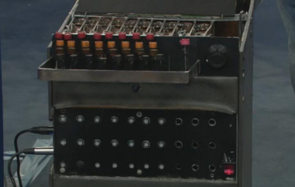
Here is an interesting bit of history sent in via MATRIXSYNTH reader, monsta poly, Charlie Douglass' "Laff Box" from 1953. It's the original device used to create laugh tracks used for TV shows. As you can see, it looks a bit like a typewriter mixed with the tape mechanism of the Mellotron. It's worth noting the Mellotron would not be released until 1954, however, the predecessor of the Melltotron, The Chamberlain was produced from 1949 to 1956, which means the "Laff Box" wasn't quite the first instrument to employ the technique. Regardless, it is a fascinating piece of gear and technology from roughly the same time period. monsta poly, sent in a couple of links on the "Laff Box" including Charles Douglass on Wikipedia, an Indiewire article on the history of the laugh track, and the following video.
The Laff Box,Laugh Box,Audience Reaction Reproducer,Laugh Track,Charlie Douglass,Canned,Fake...
Published on Dec 18, 2013 BEWARE OF SHYSTERS.COM
"The Original Historic Laff Box,Laugh Box,Recorded Studio Laughter,The Audience Response Duplicator,Sweetened,Laughter Machine..."
Note the circuit board on top appears to be an addition. Curious what it does. If anyone knows, feel free to comment.
You can also find a great video on PBS featuring the "Laff Box" being auctioned on Antiques Road show here. I was going to have it be the top video in this post, however the embed appears to give an error, so linking it here instead.
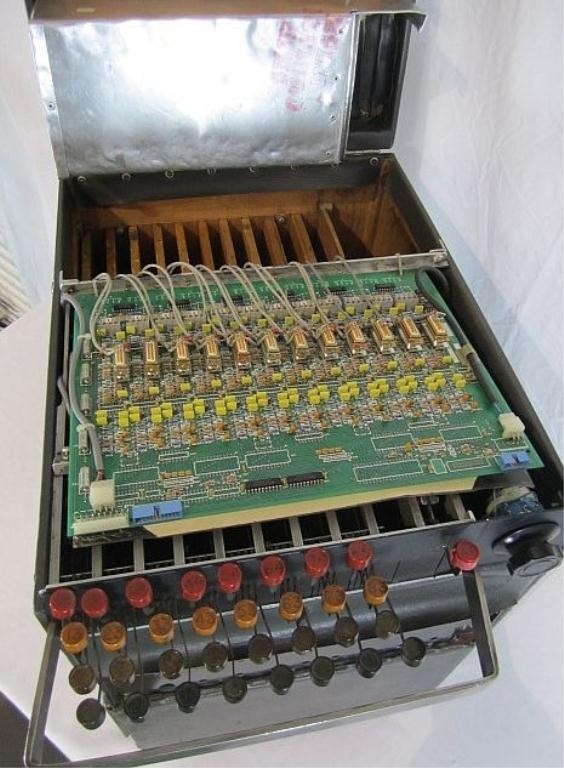
Update: here's a picture of the add-on board.


Regarding the add-on board, if I had to guess, it's probably some kind of electronic interface to the box; those square thing near the "rear" (with the thin grey cables) are likely relays that (I would guess) control solenoids to actuate keys. There are two cables per relay, so I am not sure why - but maybe two separate solenoids (or something else) - one controlled when the relay is energized, and the other when it isn't?
ReplyDeleteThe thick grey cables on the edges of the board likely supply power to the system. The blue connectors are likely for a parallel ribbon cable hookup to control the relays. There are a couple of ICs at the bottom - these may be buffers, shift registers, serial-parallel latches - but basically they are likely used to take the data in some manner, and feed it to the relay control circuits.
It's curious that there are silkscreens on the board for other components which are "unused" - this seems to indicate to me that the board isn't custom, but rather is something repurposed; again, my guess would be some kind of industrial controls relay system (perhaps scavenged from electronic surplus?).