PREVIOUS PAGE
NEXT PAGE
HOME







© Matrixsynth - All posts are presented here for informative, historical and educative purposes as applicable within fair use.
MATRIXSYNTH is supported by affiliate links that use cookies to track clickthroughs and sales. See the privacy policy for details.
MATRIXSYNTH - EVERYTHING SYNTH


© Matrixsynth - All posts are presented here for informative, historical and educative purposes as applicable within fair use.
MATRIXSYNTH is supported by affiliate links that use cookies to track clickthroughs and sales. See the privacy policy for details.
MATRIXSYNTH - EVERYTHING SYNTH
Subscribe to:
Post Comments (Atom)


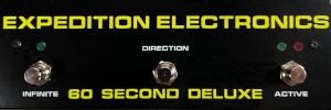


"No op amps at all..."
ReplyDeleteJust a triple OTA. Loser.
That's like saying "I walked across a field of broken glass WITHOUT SHOES!"
Just boots.
Who's the loser? Apparently you know NOTHING of the differences between an op-amp and an OTA. Just to refresh your memory, here's a bit from the "All knowing, All seeing Wikipedia".
ReplyDelete"Principal differences from standard operational amplifiers
* First, its output of a current contrasts to that of standard operational amplifier whose output is a voltage.
* Second, except for its input stage (which is a simple two transistor differential amplifier), its internal circuitry is completely different. The OTA is constructed completely of transistors and diodes; it uses no resistors or capacitors. [2]
* Third, it is usually used "open-loop"; without negative feedback in linear applications. This is possible because the magnitude of the resistance attached to its output controls its output voltage. Therefore a resistance can be chosen that keeps the output from going into saturation, even with high differential input voltages."
Take that!
I like Christmas.
ReplyDeleteMaybe nuke should look at the circuit diagrams for the VCFs in the old Roland modulars. They used OTAs. I believe that the 700 used op amps for buffers and the 100m used FETs but no op amps.
ReplyDeleteAlso, nuke can look up "fallacy" in Wikipedia to see what does and what does not constitute a valid argument.
And for the last comment of the OP/OTA discussion - i could also have used a dual potentiometer in this dirty little "design", but it was intended to be cleaned up somewhen and be usable via CV.
ReplyDeleteThe Circuit was a bit inspired by the LM13700/NE5517 application notes by the way - i just wanted to try out if it's possible to replace the usual opamps by simple JFETs as buffers between the stages - it is, very well. Just the input stage is a bit trickier when just using one JFET for this.