Title link takes you to the full scan. Here's one in color. Both mirrored here.
Update via the comments: "Hi. Thanks for sharing these schematics. And great job with the transcription. I am implementing the Hz/V-V/Oct circuit, along with a Trigger processor in my Yamaha SY2A mono synth. Works pretty well. Note : I've noticed 2 mistakes in the coloured version of the schematic. If you care to fix it, I think it may help people 'cause they'll probably, as I did, use the coloured version, since it is easier to read.
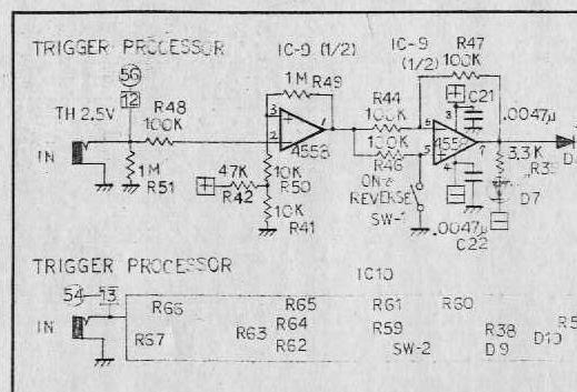
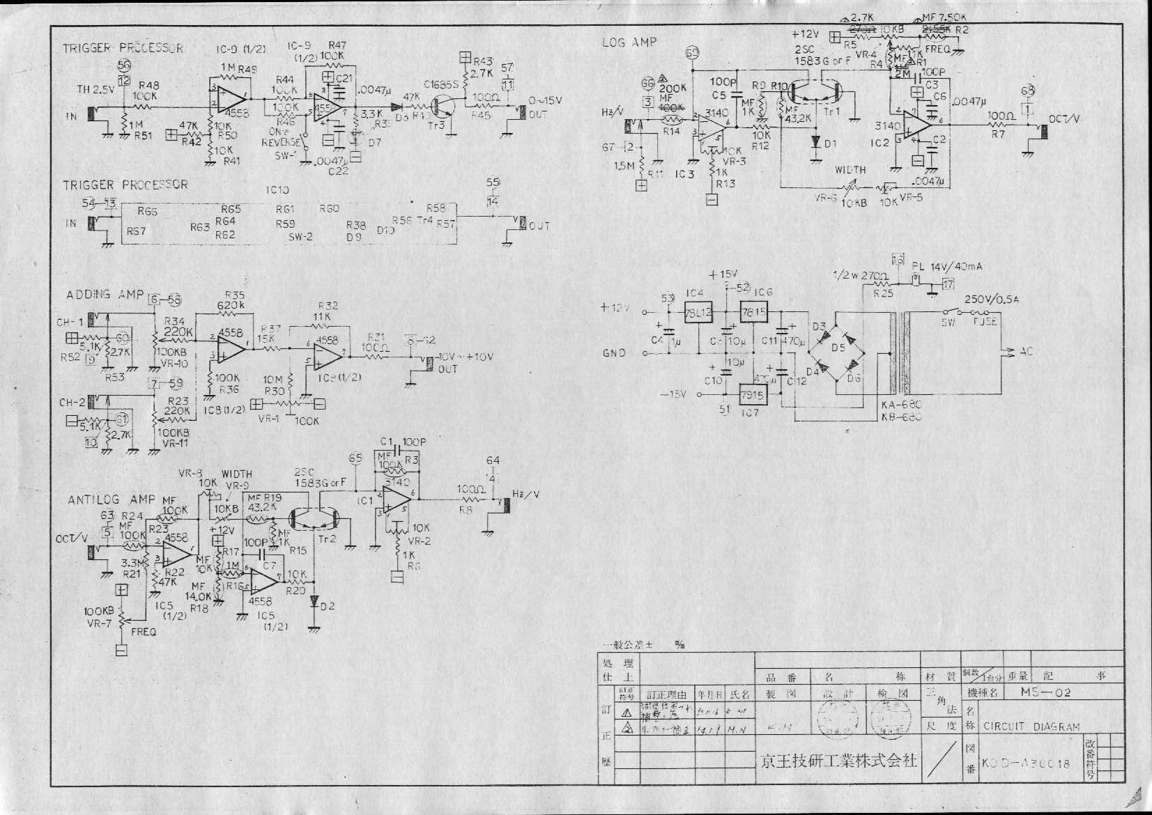
Trigger Processor :
- IC-9/10, first half : the op amp's input symbols (+ and -) are reversed. "+" should be at pin 3, and "-" at pin 2
- IC-9, sec half : The mistake is also on the original schematic. +supply pin should be 8 instead of 3."


MS-02 != MS-20
ReplyDeleteYep.... Gotta love typos.
ReplyDeleteSay what??
ReplyDeleteMS-02 = MS-02
The MS02 is Korg's Synthesiser Interface Module:
http://www.keyboardmuseum.org/pic/k/korg/m/ms02.jpg
Yeah, the post originally was titled with MS20 instead of MS02.
ReplyDeleteHi. Thanks for sharing these schematics. And great job with the transcription. I am implementing the Hz/V-V/Oct circuit, along with a Trigger processor in my Yamaha SY2A mono synth. Works pretty well.
ReplyDeleteNote : I've noticed 2 mistakes in the coloured version of the schematic. If you care to fix it, I think it may help people 'cause they'll probably, as I did, use the coloured version, since it is easier to read.
Trigger Processor :
- IC-9/10, first half : the op amp's input symbols (+ and -) are reversed. "+" should be at pin 3, and "-" at pin 2
- IC-9, sec half : The mistake is also on the original schematic. +supply pin should be 8 instead of 3.