via Bitexion on VSE
"This is copied off the Analogue Systems user manual, since they have two cloned EMS modules in their line, the filter and trapezoid. Not written by me. Part 2 comes later, it's 10 pages of tightly written text.
The most interesting parts are the part about the awful control voltage scheme internally, and the quirky DK1 keyboard. Here you go. This part deals with the VCS3 and why it is said to be an effects machine. The next parts will deal with the success and fall of the company, no time to write all that down now.
THE EMS STORY
IN THE BEGINNING
------------------
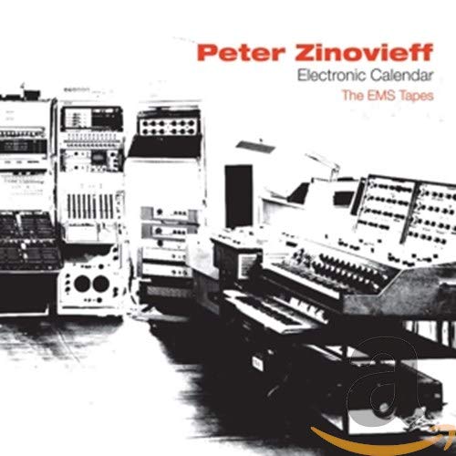
Peter Zinovieff was born in London in 1933. A geologist who filled his home with samples (rocks, not audio) he was fascinated by electronic music, and used his wealth to develop a huge voltage controlled studio that occupied an entire room at his home in Putney.
When this became too unwieldy, he enlisted the help of engineer Dave Cockerell and programmer Peter Grogno, who helped him design an enhanced system. This used two DEC PDP-8 minicomputers to control the voltage-controlled modules of Zinovieff's early synthesizers. Their "MUSYS" system proved reasonably user-friendly,with a QWERTY keyboard and a velocity sensitive piano-style keyboard, much like today's computer-based studios.
Zinovieff's ideas and instruments were incredible. Twenty years before modern computing and sequencing packages, Zinovieff's PDP-8s could store and replay compositions, complete with sound shaping parameters. His software was even capable of twisting the music into bizarre new sounds and effects. In 1968, Zinovieff and Cockerell also invented a form of computer-controlled spectral (or 'additive') synthesis, using a system of 60 resonant filters that could analyse sounds and resynthesize them.
In 1969, when MUSYS became too expensive for Zinovieff alone, he decided to offer it 'to the nation' as a free resource for the arts. To this end, he placed an advertisement in The Times. Fortunately, a gentleman named Don Banks misunderstood this offer and, in return for a cheque for £50, he asked Zinovieff to "make me a synthesizer". So, together with Tristram Cary, a composer for electronic music for TV series such as "Dr Who", Zinovieff and Cockerell created a new company, Electronic Music Studios Ltd, and produced its first synthesizer. Cockerell's "VCS1" was a hand-built rackmount unit with two oscillators, one filter and one envelope. In an era when any synthesizer was, almost by default, a huge modular, this was not thought to be adequate, so the partners enhanced Cockerell's initial ideas, designing an instrument that was small, but powerful and flexible. It was the Voltage Controlled Studios no.3- The VCS3
THE VCS3
--------------
The VCS3 is, essentially, a modular synth that comes in two parts. The synth itself - nicknamed "The Putney" because EMS was located in that part of London - contains the bulk of the audio modules. It also incorporates two power amplifiers and speakers, making it a self-contained sound-effects generator.
Oscillators 1 and 2 are the primary sound sources, and these produce a remarkable range of frequencies, from below 1Hz to around 10KHz. Osc1 produces sine and sawtooth waveforms with a form of rectifying waveshaping for the sine wave. Independent level controls allow you to select the amounts of each waveform in the oscillator's output. The second VCO also produces two simultaneous waveforms, and again it offers independent level controls for each. This time, the waveforms are pulse and triangle waves, with simultaneous waveshaping from 0% to 100% on the former, and from sawtooth to ramp wave on the latter. It's a shame that, on an unmodified VCS3, none of the waveshapers can be voltage controlled, because this would introduce many forms of PWM and dramatically increase the range of sounds available. But there it is... Once selected, a waveform is static. A third VCO is similar to VCO 2, with pulse and triangle waveforms, but its frequency range is concentrated further down the spectrum, lying between 0.025Hz and 500Hz.
An independant section on the panel contains a noise generator, with a level control and a 'colour' control that varies from predominantly low frequencies (red) through 'white' noise, and up to predominantly high frequency (blue) noise. Another section contains the Ring Modulator which, as you would expect, offers just an output level control.
Many players and writers have described the VCS3's filter as a conventional lowpass filter with an 18dB/octave slope, but they are - to some extent - wrong. For one thing, the VCS3 filter exhibits a 'knee' in its cutoff profile; the first octave above the cutoff frequency rolls off at 12dB/octave, but the slope increases to 18dB/octave at frequencies above that. Furthermore, any amount of filter resonance significantly depresses the low frequency gain, so EMS described it as a combined low-pass/band-pass device. At high Response (the EMS term for 'resonance') the filter self-oscillates. This was mind-boggling stuff in the late 60's.
If the filter is unusual, the envelope generator (which EMS called a 'shaper') and its associated VCA are positively arcane. It has six controls. The first is straightforward enough - it's the Attack, which has a range about 2ms to 1s. So far, so good. The next control is laballed "ON", but nowadays we would call this a ustain level "Hold" because it determines the length of time the envelope stays 'high' after you release the gate. Control number three is more recognizable - it's a Decay rate, with a claimed range of 3ms to around 15 seconds. The fourth knob is labelled "OFF" and it determines the delay before autoretriggering of the envelope cycle. Until you understand that this must be in the '10' position (called 'Manual') to play the VCS3 conventionally, things can get very confusing. Indeed, the envelope will auto-repeat at frequencies of up to 60Hz, which is well inside the audio range, so the 'Shaper' can also act as an LFO or even as a deep bass oscillator.
The envelope has two outputs with independent level controls. The first (and the fifrth in the 'shaper' section) is the one that confuses most people: it's the "Trapezoid" level. To understand this, just picture an envelope produced by an AHD (attack/hold/decay) contour generator. This is a shape called a trapezoid. So the Trapezoid Level simply determine the level of the envelope CV. The second level control (the sixth shaper control) is the signal level, and this controls the loudness of any signal passing through the Shaper. There is a lso a large, red ATTACK button, which we would nowadays describe as a manual Gate.
The VCS3 also provides a spring reverb with Mix and Level controls. This is a simple dual-spring device, with a maximum reverberation time of approx. 2 seconds. Unfortunately, when using the VCS3's internal speakers, the reverb howls uncontrollably before the mix gets very dense, and you can only use it to its full potential with external amplification and speakers.
It may not be obvious at first sight, but the VCS3 is a stereo synthesizer with independent output channels A and B that drive the left and right speakers respectively. These have independent level controls, panning controls, and output filter that, depending upon position, attenuate the bass or trable, or porivde a flat response.
Performance controls are limited to the enormous X/Y joystick. This has two controls that govern the X and Y ranges but, unfortunately, its maximum range is about +/-2V, so it's not often that you can plumb the extremes of any parameters it controls. There is also a
voltmeter that allows you to measure any control voltages (which are close to DC) or signal levels (which are AC) within your patches. You can even connect an oscilloscope to a dedicated 1/4" output on the rear.
THE DK1 KEYBOARD
---------------------
The separate DK1 keyboard - known as "The Cricklewood", because that was where Cockerell worked - was as radical as the VCS3 it controlled. Of course, it was monophonic (there were no poly synths in 1969) but it was velocity sensitive, allowing players to add expression in a
way that had hitherto been impossible.
You connect the DK1 to the VCS3 using a dedicated 8-way cable that provides two power rails, two CVs and a Gate pulse for the envelope shaper. To the left of the keyboard itself, two switches control the two output CVs (called 'Channels') produced by the DK1. The first of these has 'Signal' and 'CV1' positions. We'll come to signal in a moment...for now, simply understand that CV1 was what we would now call pitch CV. Hang on... doesn't CV1, and therefore channel 1, produce the same thing? Yes it does, so there's no point in having both switches set to 'CV'.
Now, let's return to that 'Signal' position. The DK1 has a built-in sawtooth oscillator and an associated VCA with frequency, 'spread, level and dynamic range controls. This is a godsend because, with the spread set to '10' the oscillator tracks the keyboard in a conventional 1:1 relationship. In other words, you can play the keyboard and, with everything else set up appropriately, you'll hear the notes that you would expect. This is not necessarily the case when you use the keyboard CV channels. This is because the keyboard CV channels enter the VCS3 through two input level controls marked, sensibly enough, Channel 1 and Channel 2. The problem arises because the 1:1 keytracking occurs somewhere between '6' and '7' on the knobs, and the exact position can fluctuate wildly with the oscillators' temperature, the time of day, and the FTSE100 index. This makes it very tricky to use the VCS3's internal oscillators for correctly pitched melodies. Every time you play the thing, and even after an hour of 'warming up'm you are constantly trimming the tuning and scaling the Channels.
Furthermore, the VCS3 doesn't confirm to either 1V/octave or Hz/V standards used by every other manufacturer, before and after. It uses internal voltages of 0.32V/octave for oscillators 1 and 2, 0.26V/octave for oscillator 3, and 0.20V/octave for the self-oscillating filter. However, because there are CV amplifiers on the internal module inputs, you need to double these figures to 0.64V/octave, 0.52V/octave and 0.40V/octave respectively for external CV sources. Argghhh!!!!
Likewise, the usual 10V peak-to-peak signal levels are eschewed in favour of 3V, 4V and 6V for the oscillators (depending on waveform), 5V for the filter, 3V for the noise generator... and so on. There was nothing about the VCS3 that we would now regard as conventional.
You might think that this is enough of the VCS3's and DK1's oddities, but you would be mistaken. This is because yet discussed its most notable characteristic: the patch matrix.
ENTER THE MATRIX
-----------------
The most important thing to note here is that the VCS3 will remain forever silent unless you stick some pins into the matrix. This is because none of the devices described are connected to eachother unless you use the matrix to determine which signal goes where. Fortunately, the 16x16 matrix allows you to connect any of the VCS3's modules to eachother. For example, let's say that you want to direct the output of oscillator 1 to output channel 1. Since the signal generated by oscillator 1 emerges from the list of sources in row 3, and the input to channel 1 is column A, you simple stick a patch pin in position A3, and the connection is made. Of course, this doesnæt preclude you from sticking more pins in row 3, and yet more in column A, so patches can become very complex, very quickly. Indeed, you can stick 256 pins into all 256 available sockets, but i doubt that it would create a sound. Also, you must remember that, at this point, you have only made a set of connections between modules. Whether you hear a sound, or whether it's a useable one, still depends on the positions on the front panel controls.
Unfortunately, there are three problems with the matrix. The first two are simple to avoid: if mistreated it can become unreliable; and it's very expensive to replace. The third is more fundamental...
The matrix is not "buffered", and this means that, every time you insert a pin into an existing patch, the actions of other patch connections will change to some degree. Let's suppose that you've spent an hour creating a complex patch and getting every knob exactly as you want it. You the decide that you want to add, say, oscillator 2 to the filter input. You insert the appropriate pin - and everything else changes. As you can imagine, this is infuriating.
Now let's turn to the patch pins themselves. These are not simple metal connectors that short between the row and column rails. They are resistors, and there are three types of these in common use. White ones (with a resistance of 2.7kOhm) are the most common, and you can use them for almost anything. However, because the resistors in the pins have a wide (5%) tolerance, they are not suitable for some jobs. In particular, two white pins inserted into I8 and J8 (CV Channel A connected to the pitch CV inputs of VCO1 and 2) will often be sufficiently different to make the oscillators track differently. To overcome this, EMS supplied red pins, also 2.7KOhm, but with 2% tolerance. The third of the common pin colours is green. These pins have a higher resistance than the others, thus reducing the amplitude of a signal considerably. Most often, you use these when you want to attenuate a control signal, such as applying a delicate amount of modulation to a pitch CV input.
If you read some of the conversations flying around the Internet, you might be forgiven for thinking that the VCS3 is no more than a glorified effects unit. In part, this is because few casual users have the patience or knowledge to squeeze conventional musical signals from the instrument. But perhaps more significantly, it's because the VCS3 has four 1/4" inputs on the rear panel - two for microphones, two for line level signals - routed to the Channel 1 and Channel 2 rows on the patch matrix. Because the VCS3 is modular, this is a far more powerful arrangement than the signal inputs on pre-patched monosynths, allowing you to use an external signal as an extra module, maybe as an audio source, a CV source, or even a Gate.
There's another reason why the VCS3 is often regarded as a sound mangler. Because its internal oscillators are so unstable, using external signals (such as generated by the DK1) is often the only way that you can play conventional melodies. So, in many ways, the VCS3's status as an "effects generator extraordinaire" is a classic case of making a virtue out of a necessity."
Scroll through these posts for more history on EMS and of course check out the EMS label below for more.
PREVIOUS PAGE
NEXT PAGE
HOME


© Matrixsynth - All posts are presented here for informative, historical and educative purposes as applicable within fair use.
MATRIXSYNTH is supported by affiliate links that use cookies to track clickthroughs and sales. See the privacy policy for details.
MATRIXSYNTH - EVERYTHING SYNTH


© Matrixsynth - All posts are presented here for informative, historical and educative purposes as applicable within fair use.
MATRIXSYNTH is supported by affiliate links that use cookies to track clickthroughs and sales. See the privacy policy for details.
MATRIXSYNTH - EVERYTHING SYNTH
Subscribe to:
Post Comments (Atom)





No comments:
Post a Comment
Note: To reduce spam, comments for posts older than 7 days are not displayed until approved (usually same day).