"Before we begin, as general background, if you need pick a project that requires matched transistor, check this out: Bill and Will's Synth Moog Transistor Matching Tester Construction. If you're building a VCO, I can supply you with monolithic matched pairs. If you're building a VCA or a VCF, you can probably get away with some rough hand matching. If you need matched diodes, check out this thread on electro-music.
OK, here's some random ideas. These are circuits that have caught my attention for one reason or another and that I would enjoy exploring more. Remember you shouldn't consider yourself restricted to picking something on this list; if you do have your own idea for a project you'd like to pursue, looking at the things on this list will give you a sense of relative scope. Or, you may not already have a project idea, and may not be interested in anything on this list per se, but reading what's here may inspire a new project idea.
Don't be scared if you see strange part numbers. A good portion of these parts are long out of production. I can suggest appropriate substitutions.
- The Rhodes Chroma VCO uses a unique "charge pump" design using an Exar 4151. Here is the service manual; in particular, the oscillator circuit is described here and the vco schematic is given in the left part of this diagram (notice each Chroma voice board has two VCO's; you'd want to build just one). The pitch input is labeled as "PITCH" A or B, and the sawtooth output is found at pin 3 of the 4151. Here are some notes about one person's experience building it. (For a one-person project, I'd suggest just buffering the sawtooth output and not worrying about the rest of the waveshaping circuitry, and I'd suggest the one in the upper-left corner that is missing the sync circuitry; for a two-person project, I'd suggest doing in the one in the lower-left corner, which includes the sync circuitry, and also building up the sawtooth-to-pulse waveshaper. In either case, I'd leave out the 4011-based ring modulator, and just bring the various outputs to the front panel instead of using the 4052 switch.)
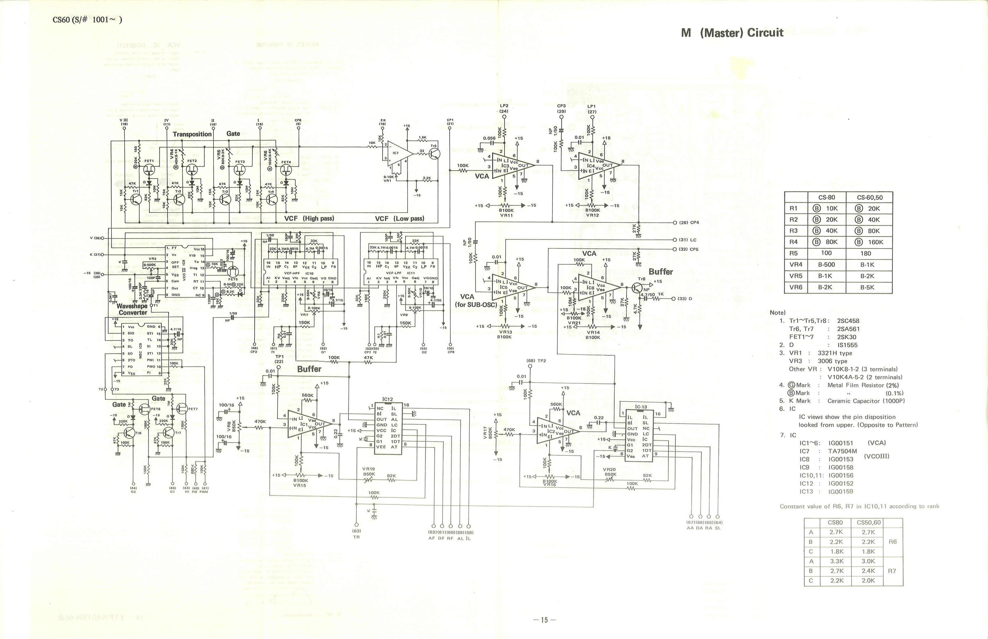
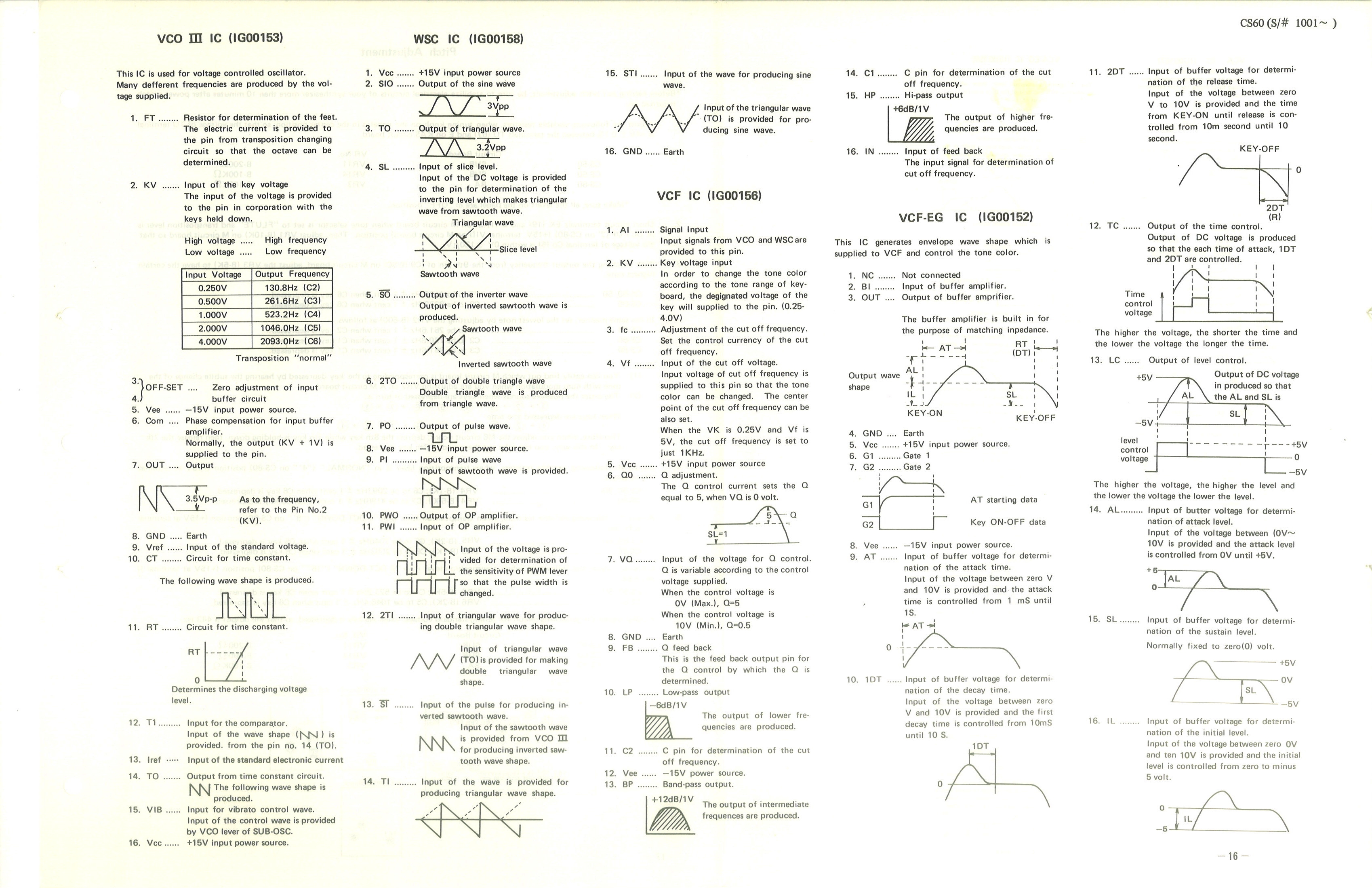
- The Yamaha CS-80 filter consists of two cascaded state variable filters, one highpass and one lowpass. You can find them on this schematic, in the right part of the diagram, labeled as VCF high pass and VCF low pass. They are known for sounding particularly smooth and creamy, perhaps because of a couple of extra parts that Yamaha threw into the 2nd-order feedback loop. They look quite compact ince they are using custom Yamaha IG00156 chips. Here is a high-level block diagram of the CS-80 VCF, and here's Juergen Haible's SPICE analysis. (The SPICE schematic looks a bit weird but don't let that scare you - the triangle {gm1} symbol combined with the boxes with the little current sources in them appear to be his way of specifying an OTA, and the boxes with the little voltage sources in them appear to be regular op amps.) You can also find a similar filter structure in the CS-50 (see schematic here) and the CS-60 (see schematic here). I haven't looked at these closely enough to see if these filter circuits are identical, and if not, what differences there are. I've found descriptions of the IG00156 here and here (see page 19).
I think it would be interesting to try to replicate this circuit. It looks to me like the IG00156 basically had some OTA and buffers and an expo, and we could guess what is where, and build it using LM13700s and a voltage-to-current expo converter cribbed from any number of sources. If this sounds interesting, let me know and I will meet with you and we can try reverse engineering the circuit together; I have a pretty good idea of how to do this. (The CS-80 has two SVFs, with the highpass output of the first going to the lowpass output of the second. A good one-person project would be to do one of these filters - maybe bring out all three outputs. A good two-person project would be to do both filters, wired CS-80 style, with the highpass feeding the lowpass.)
- Like the Yamaha CS-80 described above, the Roland Jupiter-6 has a filter consisting of two cascaded state variable filters, as you can see in this schematic. Each filter has an electronic switch that lets the musician choose between the highpass and lowpass outputs, so you can have a 4-pole-highpass filter, a 4-pole-lowpass filter, or a bandpass filter consisting of a combination of the 2-pole and 4-pole filters. You could replace the electronic switches with ordinary mechanical switches. Notice that the voltage controlled resonance is the same for each SVF. (A good one-person project would be to do one of these filters - maybe bring out all three outputs. A good two-person project would be to do both filters, wired Jupiter 6 style, with the highpass feeding the lowpass.)
- There's this great thread on electro-music about building a Korg MS-20 sytle VCO, which includes some schematics of a few versions of a modularized adaptation. It has a sawtooth core, but it's a "thyristor" design that is different than the sawtooth core we covered in class. (The sawtooth core would be a good one-person project; a full-featured oscillator that also included the various waveshapers from the MS-20 would be a good two-person project.)
- The Buchla 148 generates harmonics from a fundamental triangle wave through a series of strange waveshaping circuits. These circuits are odd; they create deadbands, not the way we saw in class, but through op amp circuits with diode bridges in the feedback loop. They are quite strange. Let me know if you'd like to take a look at some of them and try getting them to work. (This could be a one-person or a two-person project, depending on how many circuits are tackled.)
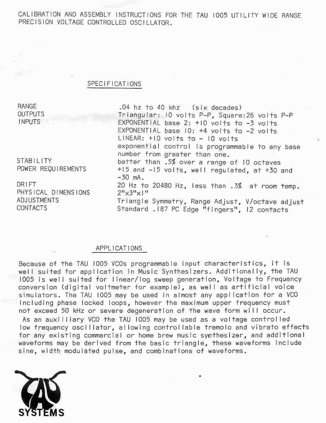
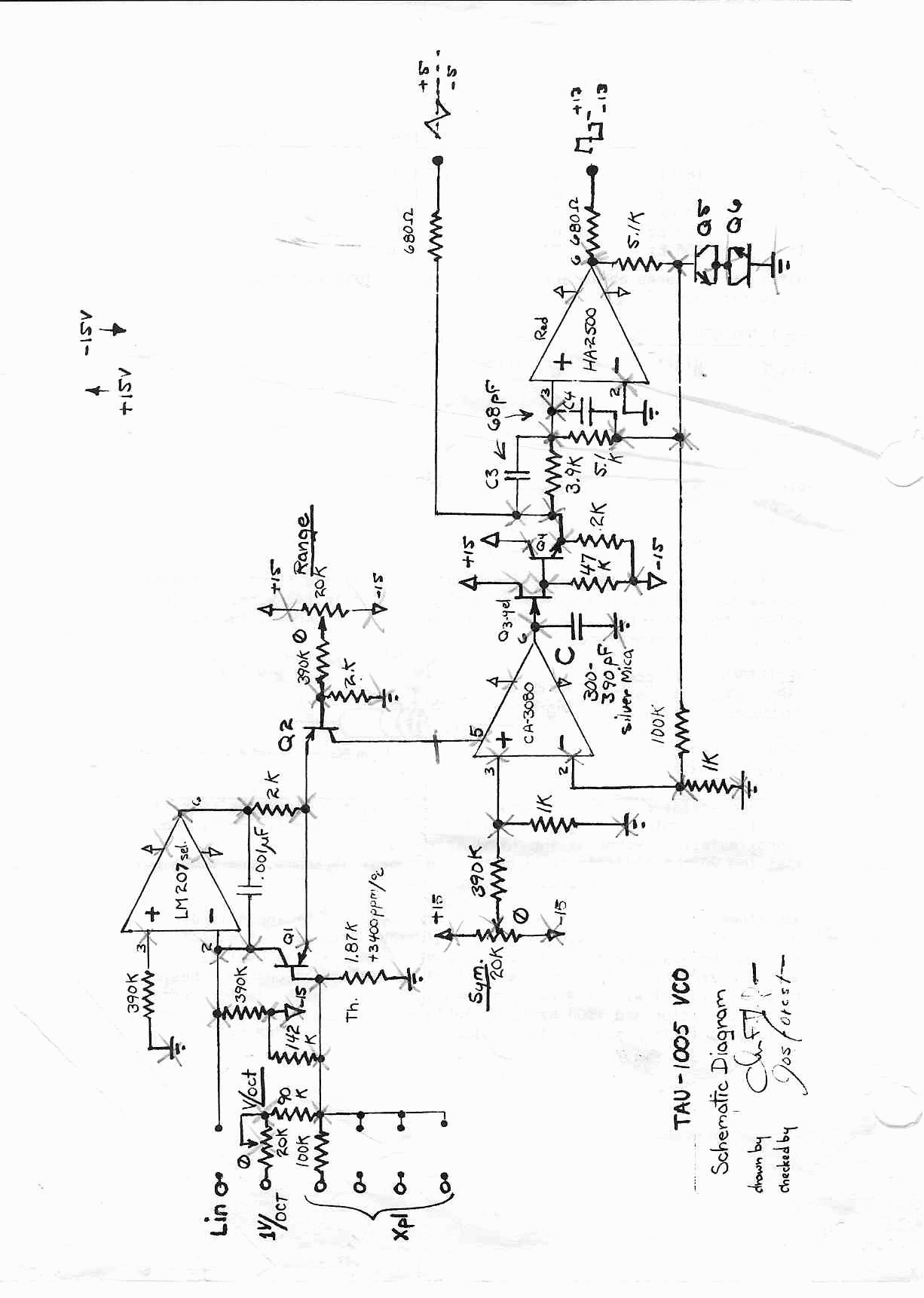
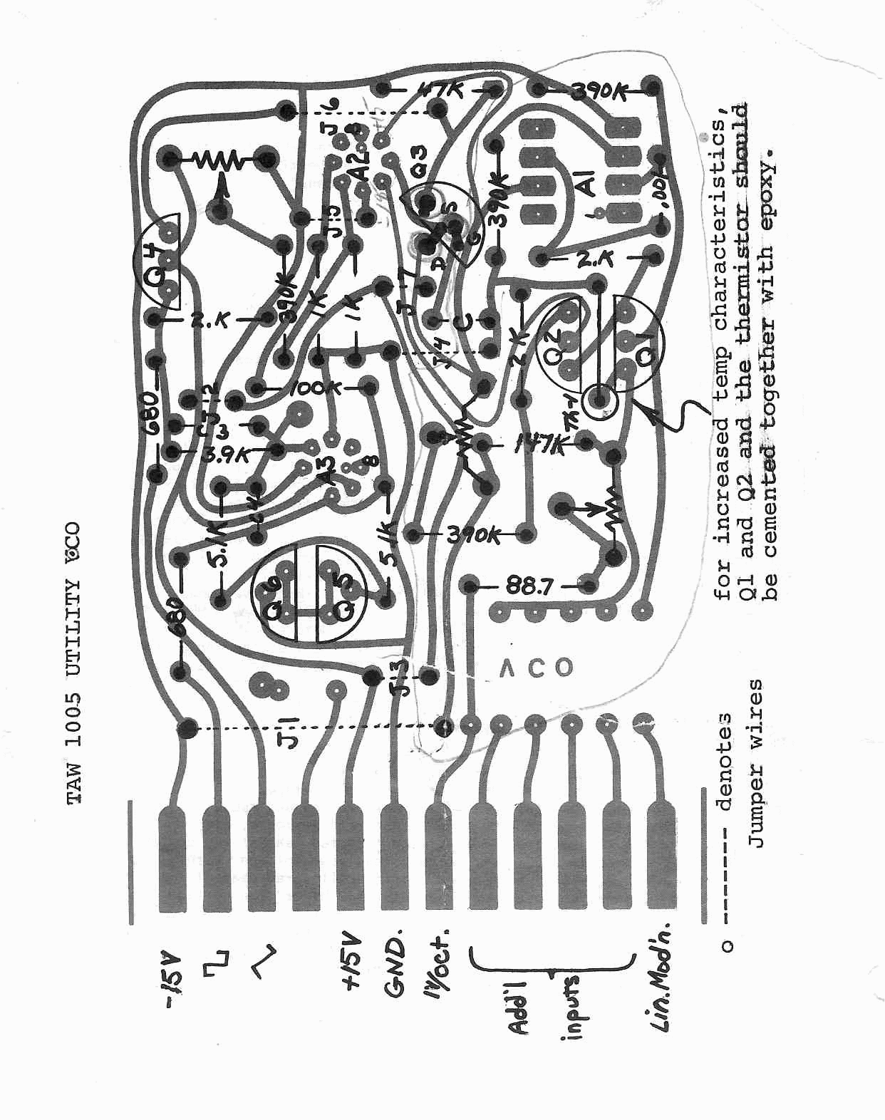
- I ran across information about the Tau 1005 Utility VCO on Jim Patchell's website. I can't seem to find any information about this company "Tau Systems" - my google fu is failing me. (Juergen Haible cloned the "Tau Pipe" phasor a while back, so most google hits are realted to that). Anyway, looking at the schematic, you'll see it's a triangle core like the Buchla 259 core we discussed in class, except a CA3080 is used instead of the "roll your own" 4-transistor OTA Buchla uses. The HA2500 op ap is acting as the comparator, and the FET and BJT at the output of the 3080 are acting as a buffer. I think the weird configuration of Q5 and Q6 is acting as a voltage clamp. It appears to have been intended to be some sort of plug-in module for a bigger circuit. (This would be a good one-person project.)
- The Korg Delta has a rather interesting VCF; you can find it in the upper right corner (once you flip it sideways) of "Section 4: Circuit Diagram" in the service manual. It's like a 4 pole cascade, using LM13600s (we would use LM13700s), but the feedback loops are weird, making it look kind of Sallen-Key-ish. I'm not sure what's going on in this circuit but I bet it sounds interesting. Anyway, it looks like the audio input is buffered by IC-6 (or IC-8? I am having trouble reading it), and immediately hits a LP/BP decision switch Tne the audio output is the output of the last stage. The 15K resistors R122, R127, R132, and R137 just make sure current is flowing through the Darlington buffers. The main control voltage is in theupper right, labeled "ext fc," along with the "Cut freq" pot - you could probably drop the "Joystick" input. If this looks fun, I will meet with you and hammer out the details and go over the smeared and confusing parts of the schematic. You should also look at EFM's version of this filter. (This is a somewhat big circuit, but probably still doable by one person.)
- The Roland Jupiter-4 filter consists of a 1-pole highpass followed by a typical 4-pole-lowpass-with-feedback. You can find it in the service manual; it's on the top of one of the page that says "module board," about 40 pages in. The LPF part is quite similar to the polyfusion lowpass VCF we looked at. You'd probably want to simply the various bits of control current generation circuitry. If this one sounds interesting, ping me and we will brainstorm. (This is a big circuit; probably would make a good two-person project).
- We've discussed how some manufacturers used diodes (or diode-connected transistors) instead of BJTs as way to "get around" the Moog ladder VCF patent. One such company was Roland. A couple of years ago, one of my EMS students built the Roland 100 diode ladder VCF, and it sounded totally badass. So how about one of the others? You could try the SH3 filter (which actually has five stages instead of the usual four), or the SH1000 filter (to make sense of "Pack #2" you will need to see how it fits in to the big picture, as seen on the second page of the full SH1000 schematics). Or, you could try the 4-pole lowpass VCF from the SH-5.
- OK, I just had a crazy idea... We've looked at four-pole-LPF-with-feedback cascades using OTAs in place of resistors. We'll also briefly talked about vactrols, which are light dependent resistors combined with a light emitting diode. How about putting a single LED in the center of four LDRs, placed equally spaced around the LED? (Some very old guitar pedals, such as the Univibe, used this idea). Those LDRs could then replace the resistors, and you could control all four stages at once just by changing the current through a single LED. It would be a sort of make-your-own super-vactrol. You'd probably want to cover up the LED/LDR setup somehow so external light wouldn't effect it. (This would be a decent one-person project).
- The so-called "biquad filter" (see Figure 5 of this ap note) is a variation of the state-variable idea. Notice it consists of a single-pole filter and an integrator; the op amp in the middle is just an inverter. I'm not aware of any synth designs using this topology; is should be pretty easy to make this voltage controlled via OTAs. The single-pole part could be done easily using the single-pole OTA we've seen in lecture, and we've seen many voltage-controled OTA integrator designs. I can help with the design. (This would make a good one person project, especially for someone yearning to do a more original design.)
- I came across a youtube video demonstrating the Farfisa Syntorchestra, which sounds fantastic. There seem to be two VCF circuits in the schematics (you'll have to rotate them clockwise by 90 degrees in your PDF viewer for them to make sense), one in the "Poli" section (upper right corner of page 6) and one in the "Mono" section (upper right corner of page 8). They're quite strange. It looks like they're using JFETs as variable resistors; this is usually easy to do in a predicable way if one side of the "resistor" is grounded, but here they're "floating," which is likely to induce all sorts of odd behavior. The Poli one seems to be an cascade of two RC stages, but without buffering between them, so the poles of the filter will be spread out a bit, and I don't seem to see any feedback. The Mono version seems to have a feedback loop from the output back to the input, but that feedback loop itself has some unbuffered RC stages in it, and there's a swtich that you can use to switch this feedback loop in and out. I'd love for someone to rig this up and hear how it sounds! (This would probably make a good one person project.)
- Sorting through my hard drive, I found this interesting transistor ladder that uses PNPs instead of NPNs. I can't recall where I found it! (Once you add in a current source, this would get pretty big, suggesting it would be a good two-person project.)
- Guitar effects, like wah pedals and distortion circuits, are often a great source of ideas; sometimes you can take such an effect and replace variable resistors with vactrols or JFETs (used as a voltage controlled resistor). This could be a one-person or a two-person project, depending on size and complexity of the circuit you want to build.


No comments:
Post a Comment
Note: To reduce spam, comments for posts older than 7 days are not displayed until approved (usually same day).