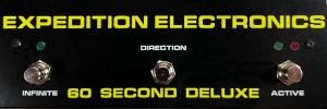
 Great shot of the inside via Cafe 80
Thursday, January 07, 2010
NAMM: BugBrand CLK2A - Divisions
YouTube via BugBrand
"Here's the new CLK2A Clock Divider with integer divsions from 2 to 9. Check the Modular pages at www.bugbrand.co.uk for full info!"
AELITA demo by syntezatory.prv.pl
YouTube via Jexus
"Demo of Aelita, the soviet analog synth. All melodies & sounds by WC Olo Garb. Video editing by WC Olo Garb. ||| Syntezatory.prv.pl Videos: showing you not what a synthesizer can do, but what a man can do with a synthesizer."
astat and volfram diy synths demo
astat and volfram diy synths demo from ::vtol:: on Vimeo.
astat + tr-626 from ::vtol:: on Vimeo.

 more info and demos- http://samoletuvvp.narod.ru/vto/diy/astat.html
NAMM: Doepfer A-132-4 Quad exponential VCA / Mixer
 via Doepfer
"Module A-132-4 contains four identical voltage controlled amplifiers (VCA) with exponential control scales. Each VCA has two control voltage inputs (C1, C2), a signal input (In) and a signal output (Out). The control voltage inputs C1 and the signal inputs are normalled, i.e. the corresponding input signals of unit #1 are connected to switching contacts of unit #2. Those of unit #2 are normalled to unit #3 and so on. In addition the sum of all four outputs is available (bottom left socket with the sum sign). Therefore unit #4 has only one control voltage input (only C1, no C2). If desired this socket can be jumpered as control voltage input 2. But then the sum signal is no longer available as a socket (only as an internal pin). For each VCA output a jumper is available that determines if the output signal of the corresponding VCA is added to the sum signal. From the factory all four jumpers are set (i.e. all four VCA output signals are added). By removing of one or more of the jumpers one can choose which VCA output is added to the sum. The jumpers can be replaced by switches too.
Technical details:
The control scale for each VCA is about 12dB/V (i.e. 1 V CV decrease corresponds to 12dB level decrease and 1 V CV inrease corresponds to 12dB level increase). 0V CV corresponds to about -60dB (i.e. about attenuation by 1000). +5V CV corresponds to about 0dB (i.e. no attenuation or amplification = 1). The full attenuation/amplification range is about -90dB ... + 20dB. Attenuations below -60dB require a negative control voltage, amplifications beyond 0dB require a control voltage more than +5V.
DIY remark: the control scales and the 0dB point can be modified by changing resistor values. We will publish the corresponding resistor positions and values.
This is a preliminary information about the planned module. The features are still subject to change and all specifications are still preliminary without any obligation ! We will probably add some jumpers to enable different normalling options (e.g. serial connection of VCAs)."
PREVIOUS PAGE
NEXT PAGE
HOME










© Matrixsynth - All posts are presented here for informative, historical and educative purposes as applicable within fair use.
MATRIXSYNTH is supported by affiliate links that use cookies to track clickthroughs and sales. See the privacy policy for details.
MATRIXSYNTH - EVERYTHING SYNTH


© Matrixsynth - All posts are presented here for informative, historical and educative purposes as applicable within fair use.
MATRIXSYNTH is supported by affiliate links that use cookies to track clickthroughs and sales. See the privacy policy for details.
MATRIXSYNTH - EVERYTHING SYNTH


