Showing posts sorted by date for query Doepfer A-196. Sort by relevance Show all posts
Showing posts sorted by date for query Doepfer A-196. Sort by relevance Show all posts
Thursday, November 26, 2009
PLLesque
YouTube via neandrewthal
"This is not intended to be a musical performance but merely a demonstration of a voltage controlled oscillator I patched up from several NOR gates and lag processors whose mistracking of an applied control voltage creates pleasant artifacts reminiscent of the Doepfer A-196 Phase Locked Loop."
Sunday, November 22, 2009
Study Music
Study Music from Pete Shambler on Vimeo.
"A patch that was left up and slowly tweaked over three or four weeks while I was studying for the GREs.
This is where it was the day that I took the exam.
Voices:
1. Tip Top Z3000, with CV from a Doepfer 160/138c combo sequencer, and FM from a Make Noise Maths (the first, audio rate channel of which is FMing the second, audio rate channel).
2. Bubblesound uLFO (which is receiving CV from a Voice of Saturn Sequencer), fed into a Doepfer 196.
3. A Boss Dr. Sound ("clap" preset), being triggered by the 5 and 8 steps of a Doepfer 161 (via a DIY "OR" logic gate).
The square out from a Plan B Elf LFO is the master clock of the patch. It is multed to (a) the Trig In on the 160, (b) the Clock In on the VoS Sequencer and (c) the CP4 input on a Doepfer 143-1.
The Envelope 1 out on the 143-1 is patched to the CV in on the top half of a Doepfer 132-3 (the Z3000/Maths voice); the Envelope 3 out is patched to the CV in on the bottom half of the 132-3 (the uLFO/PLL voice). Envelope 4 is sent to the Signal In on the first Maths channel.
theshamblers.blogspot.com"
LABELS/MORE:
bubblesound,
Curious Inventor,
Make Noise,
Plan b,
TipTop Audio,
Video,
Voice of Saturn
Tuesday, August 18, 2009
PLL guitar tests - round one
PLL guitar tests - round one from Pete Shambler on Vimeo.
"Someone on the boards requested a demo of a guitar running through a Doepfer A-196 PLL. With zero prep and very few chops, this is what it sounds like.
Patch:
Guitar --> A-119 External In
A-119 Audio Out --> A-196 PLL Phase Comp. Signal Input
A-196 VCO Out --> A-132-3 VCA Signal Input
A119 Envelope Out --> A-132-3 CV In
A-132-3 Signal Out --> computer
theshamblers.blogspot.com"
PLL guitar tests - round two from Pete Shambler on Vimeo.
"Here are a few passes, each without and then with fuzz (a BYOC Mighty Mouse pedal). The extra harmonics from the pedal really animates the PLL!"
via Leisure Cove
Monday, July 13, 2009
A100 Motorik rhythm
A100 Motorik rhythm from Peter Speer on Vimeo.
"I wanted to use our still-new Doepfer A-118 Noise source in a drum pattern. This is the result.
Here's the patch:
The envelope generator on the Moog Rogue is set to auto-trigger itself.
The Audio Out from the Moog Rogue is sent to the Symmetrical input on the A-119 External Input, only to trigger its Gate output (the Audio Out on the 119 is not used).
The Gate Out from the A-119 is sent to a multiple, and from there to:
1. The Trig. In on an A-160 Clock Divider
2. The Gate In on an A-140 Envelope Generator
The /4 output on the 160 is triggering a Boss Dr. Pad (Snare 1 setting). The output from the Dr. Pad is sent to the mixer (off screen).
The /8 output on the 160 is triggering the first envelope on the A-143-1 Complex Envelope Generator (set to Attack-Decay mode) the output of which is opening the bottom VCA on the A-132-3 Dual VCA. The output on the bottom VCA is sent to a mixer (off screen).
The CP2 gate out on the 143-1's second channel (set to LFO mode) is patched to the CV In on an A-150 Dual Voltage Controlled Switch (here acting as a VCA). The output of the 150 is send to the mixer (off screen).
The triangle output from a Plan B ELF LFO is sent to a Frostwave Resonator's input, the output of which is connected to a Frostwave Blue Ringer. The Ringer's output is patched to the Input on the upper 132-3 VCA; the output of the upper VCA is sent to the mixer (off screen).
The White Noise output from the 118 is sent to the In 2 input on an A-196 Phase Locked Loop. The Phase Comp. Output from the 196 is sent to the first Input on the A-150. The second input is left unpatched.
The Colored Noise output from the 118 is sent to the Input on the bottom 132-3 VCA.
The first output on the 140 is opening the upper 132-3 VCA.
The second output on the 140 is sent to a multiple, and from there to:
1. the Low Pass Frequency CV In the Resonator
2. to an attenuator, and then to the CV In on the Ringer
I think that's everything. Two A-118 noise channels, one Dr. Pad channel and one M37-->filter-->ring modulator channel. Panned for stereo but otherwise no outboard effects used.
theshamblers.blogspot.com"
A-118 Noise from Peter Speer on Vimeo.
"I could listen to this all day!
We just got a Doepfer A-118 Noise and Random Voltage module. It's great!!
In this patch, the Colored output from the 118 is being fed into a channel on the A-132-3 VCA. The Random Voltage output from the 118 is being multed and sent to:
A. the Gate In on a A-140 Envelope Generator (the output of which is opening the VCA)
B. the Trigger In on an A-160 Clock Divider (the /4 and /32 outputs are sending CV to the two halves of an A-150 Dual Voltage Controlled Switch, strictly for blinkenlights purposes)
C. the CP3 In on an A-143-1 Complex Envelope Generator (the Mix Out of which is modulating the Low Pass Frequency on a Frostwave Resonator)
The output from the VCA is sent to the Audio In on a Frostwave Resonator filter; the Resonator is sent into a Frostwave Blue Ringer ring modulator; the output from the Blue Ringer is sent to a mixer, and from there to the computer.
The audio sync is a hair off. Please accept my apologies.
We recommend the A-118. I'm already finding it to be more useful than I'd anticipated!
theshamblers.blogspot.com"
Sunday, May 10, 2009
PLL Ringmod
YouTube via boobtube356
"Doepfer A-196 PLL tracks Plan B M15 VCO. PLL output passes through Plan B M12 bandpass filter and then is ring modulated with the M15 sine output. The result goes to the Makenoise QMMG. The background is a Cwejman VCO-6 sine going to Doepfer A-137 wave multiplier, then ring modulated with Cwejman MMF-1. The result goes to the Cwejman VCA-4MX and is then panned at audio rate by a Cwejman VCO-2RM. Sequence is from Doepfer A-160/1, A-152, A-143-3 and Plan B M14."
Saturday, May 09, 2009
Ratcheting VCS and PLL
YouTube via boobtube356
"Doepfer A-196 PLL tracks a simple sequence. The output goes to a PlanB model 12 filter in bandpass mode, and then on to the MakeNoise QMMG in low pass gate mode. The QMMG is modulated by the Cwejman ADSR-VC2. The ADSR is triggered by the PLL Phase Comp. output, which is getting smoothed out by the Bananalogue VCS, then sent to the Doepfer A-156 quantizer. The quantizer generates triggers for the ADSR as the VCS output varies. The Phase Comp output from the PLL is very unstable, even with the VCS, so the ADSR fires rapidly. The VCS is receiving rise and fall modulation from the original pitch cv coming out of the sequencer. The sequencer is Doepfer A-160/1 to PlanB M14."
Sunday, April 19, 2009
555 PLL
555 PLL from Peter Speer on Vimeo.
"Running a 555 oscillator through a pair of Frostwave pedals (Resonator and Blue Ringer), which are being controlled by the modular.The Low Pass Frequency on the Resonator is being controlled by the Triangle output of the ELF LFO.
The frequency on the Blue Ringer is set low enough to act as an LFO of sorts. It's receiving CV from the /2 output of a Doepfer A-160.
The output from the ring modulator is sent to the A-119 for amplification. The first of the A-119's outputs is sent to Channel 1 on the mixer. The second A-119 output is sent to the Signal Input on a A-196 PLL, and from there to Channel 3 on the mixer.
The bass drone is a Moog Rogue, multed to the two halves of an A-132-3. The Square output from the ELF LFO is triggering the first channel on the A-143-1, which is opening the first VCA. The CP3 output on the A-143-1 is gating the A-140, which is opening the second VCA.
theshamblers.blogspot.com"
Saturday, March 07, 2009
First night with the PLL
First night with the PLL from Peter Speer on Vimeo.
"Goofing around with the Doepfer A-196 Phase Locked Loop module a few hours after it arrived.
Patch:
--Voice of Saturn Sequencer CV Out to Freq CV on Plan B ELF LFO
--ELF LFO Square Out to Trig In on Doepfer A-160 Clock Divider.
--ELF LFO Triangle Out to In 2 on PLL
--/64 Out on A-160 is triggering the first channel on the A-143-1 Complex Envelope Generator (all channels set to AD mode)
--Mix Out on A-143-1 to Gate In on A-140 ADSR
--/32 Out on A-160 is retriggering the A-140
--Output from A-140 sent to CV In on A-132-3
--Comparator Out on A-196 to Input on 132-3
--Output from A-132-3 to computer
theshamblers.blogspot.com"
Sunday, February 22, 2009
PlanB Model 12 as VCA
YouTube via boobtube356
"PlanB Model 15 saw output goes to PlanB Model 12 in LP, high Q mode. Cwejman ADSR modulates the M12 cutoff frequency. Result goes straight to speakers. Percussion sounds are two VCOs being ring modded with the 2 and 6 osc ouptuts on the Doepfer A-117. "Lead" part is the Doepfer A-196 PLL trying to track a VCO that is trying to track the PLL, and the result goes to Cwejman VCEQ-3 (see also PLL Arabesque). Sequencing is Doepfer A-160/161, A-152, and A-138. No manual adjustments made during this clip."
Saturday, February 07, 2009
02072009
02072009 from dougcl on Vimeo.
"Doepfer A-117 amplitude modulated by audio rate square wave from A-143-3. Bass kick is Cwejman VCO-6 sine with envelope pitch modulation. Bass part is Cwejman VCO-2RM FM configuration to QMMG. Midrange is Blacet Miniwave. Doepfer A-196 adds some melody to the top. Adjustments being made are to the Miniwave bank select and PLL pitch. Doepfer A-160/1, A-152, and A-138 handles the sequencing."
Sunday, December 21, 2008
PLL Melody
YouTube via boobtube356
"Doepfer A-196 PLL attempts to track a simple sequence. PLL output goes to a Makenoise QMMG modulated by a Cwejman ADSR-VC2. Adjusments to the PLL demonstrate the basics of this module."
Sunday, November 16, 2008
PLL Arabesque
YouTube via boobtube356
"Doepfer A-196 PLL attempts to track a pulse width modulated A-111. An A-147 is the modulation and clock source. The result passes through a Cwejman VCEQ-3."
Wednesday, November 12, 2008
DOEPFER A-188-2 TAPPED BBD DELAY
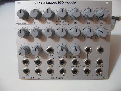 via this auction
"A-188-2 is another module that is based on a so-called Bucket Brigade Device (BBD). If you are not familiar with BBDs please refer to the A-188-1. There you can find some details about this special type of circuits.
The main difference between A-188-1 and A-188-2 is the type of BBD circuit that leads to completely different module principles and sounds. The A-188-1 uses different single BBD chips with one signal input and one signal output only. In contrast the A-188-2 uses as so-called tapped BBD that has available six outputs - the so-called taps after the BBD stages 396, 662, 1194, 1726, 2790 and 3328. In the A-188-2 we use this special BBD circuit (MN3011) to obtain these module features:
The module has available two separate mixing sub-units. For both mixers the levels and polarities of each BBD output can be adjusted to obtain two different mixtures of the BBD outputs. A new type of potentiometers with center detent and center terminal is used for the BBD mixing controls to have a better feel for the neutral position. Each mixer has a wet/dry control at its output that allows choosing between the pure input signal (original), the BBD mix or anything in between. The two outputs can be treated as stereo outputs but it is also possible to use one of the outputs for other applications (details in the next paragraph).
 The A-188-2 has a feedback section available that is very similar to the one in the A-188-1. But as we now have 6 different BBD outputs available 6 different feedback types are possible. The feedback input socket is normalled to the "396" output (not to "1194" as shown in the scheme, the front panel is correct). But by patching the feedback socket to any of the single output sockets another BBD tap can be used for the feedback to obtain different sounds. Even external feedback processing is possible (e.g. with a VCA for voltage controlled feedback). The feedback control has polarizer function, i.e. the neutral position is at the center. Left from the center the feedback signal is subtracted from the input signal, right from the center it's added (negative/positive feedback). Even for this potentiometer the new version with center detent is used.
A special feedback can be obtained if one of the mix outputs is used for the feedback function. In this case for each tap the positive or negative feedback share can be adjusted. This leads to multiple peaks and/or notches in the frequency response of the module.
For each tap of the BBD a separate output socket is available. These sockets can be used for changing the feedback loop - as mentioned above -, for voltage controlled mixing of the taps - e.g. with the voltage controlled mixer A-135 or other applications that require access to each single tap.
The A-188-2 uses the same high speed VCO (HSVCO) for the BBD clock as the A-188-1. The clock and consequently the delay time can be controlled manually (delay control) and by the two control voltage inputs CV1 and CV2. The sensitivity of CV1 is approximately 1V/oct. CV2 is equipped with a polarizer (a new type of potentiometers with center detent). The HSVCO has a clock output available that is normalled to the clock input socket. These sockets can be used to link different BBD modules and to run them with the same clock. But even other applications with frequency dividers (e.g. A-163) or PLL (e.g. A-196) are conceivable. A voltage composed of the manual delay control, CV1 and CV2 is available at the CV out socket, e.g. to control an external clock suppression filter as the A-188-2 is not equipped with such a filter (same as for the A-188-1)." more info on the Doepfer website.
Friday, August 29, 2008
PLL Detuned Unison
YouTube via boobtube356
"Two Doepfer A-111's one Cwejman VCO-6 and A-196 PLL in unison. The PLL is hitting the lower octaves and missing on occasion creating an unpredictable detuning."
Sunday, August 10, 2008
Min/Max Melody II
YouTube via boobtube356
"Same patch as before, except now the A-111 output paths are separated. The min part A-111 is now feeding a square wave to the Doepfer A-196 PLL, and the A-111 pulse width is being sine modulated in time with the notes. The PLL output is going to the Cwejman MMF-1 (now in dual-peak bandpass mode). The max A-111 is now feeding the Cwejman VCEQ-3 and then on to the Doepfer A-121 (low pass). The PLL gives the bass line its crazy character, as it has been tuned so that it can't keep up with the square wave pitch changes. Narrowing the pulse widths to zero in the meantime is not helping either."
PREVIOUS PAGE
HOME






© Matrixsynth - All posts are presented here for informative, historical and educative purposes as applicable within fair use.
MATRIXSYNTH is supported by affiliate links that use cookies to track clickthroughs and sales. See the privacy policy for details.
MATRIXSYNTH - EVERYTHING SYNTH


© Matrixsynth - All posts are presented here for informative, historical and educative purposes as applicable within fair use.
MATRIXSYNTH is supported by affiliate links that use cookies to track clickthroughs and sales. See the privacy policy for details.
MATRIXSYNTH - EVERYTHING SYNTH
