
Showing posts sorted by relevance for query GND-1. Sort by date Show all posts
Showing posts sorted by relevance for query GND-1. Sort by date Show all posts
Friday, November 11, 2022
Speak and Glitch GND-1 circuit bent speech chip synthesizer
video upload by GND-1
"Here's a short promo for our new Speak& Glitch GND-1, a Circuit Bent Speech Chip Synthesizer unlike any other. Based on an accurate emulation of the speech chip inside the popular Speak and Spell game, the GND-1 pushes into previously impossible circuit bending realms letting you create loops, rhythms and synth sounds in totally new ways.
In addition to the stereo audio output from the synth chip, the MIDI-out rhythm generator on the GND-1 was driving a software 808 drum machine. But it can drive any midi compatible device, whether it's software, hardware, or even mechanical, both via USB midi and a dedicated 5-pin DIN connector.
See richardvanhoesel.com/gnd1 for more info.
p.s. the 'flickering' OLED display on the GND-1 in the video is just a video artifact."
Wednesday, January 21, 2015
Korg MS-20m Monophonic Synthesizer Kit and SQ-1 Step Sequencer Video & MS-20m Details
Uploaded on Jan 15, 2015 Korg
"The new MS-20m and SQ-1 open a whole world of analog experimentation. Connect, sync, and sequence all your gear with the flexible SQ-1 Step Sequencer, and take the famous MS-20 sound to new levels with the FM and sync features of the tabletop MS-20m"
Note the SQ-1 comes included with the MS-20m kit. The MS-20m has a selectable filter switch on the front panel while the original MS-20 kit had to be set internally. There are number of additional improvements outlined directly below. [Details on the SQ-1 just posted here]. Fun little bit of trivia is you can see SN 000001 on the back image below. Often there is no serial number in promo shots. Thought it was kind of neat and adds to the history of whomever this particular unit ends up with. Also note it's lower case "m".
 First, the enhancements over the original:
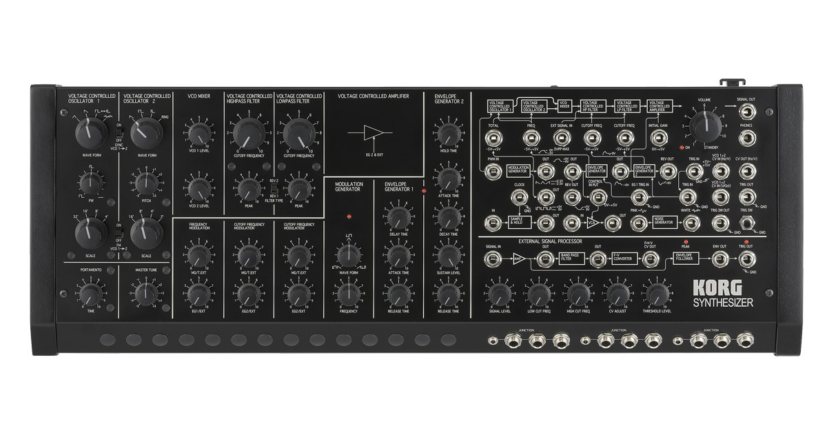 "Carrying on the distinctive synthesis of the MS-20, the MS-20M features additional improvements in both looks and functionality. Extending to detailed aspects of the design, the sound-creating possibilities have been dramatically boosted, making this sound module even more attractive and raising it to an even higher state of completion.
 SYNC ON/OFF switch allows oscillator sync
Oscillator sync forcibly synchronizes the phase of VCO1 to the phase of VCO2, producing a powerful sound with complex overtones.
 FM ON/OFF switch allows frequency modulation
The VCO1 waveform can be used to frequency-modulate the VCO2 waveform (FM or cross modulation), creating vibrato effects or extreme metallic sounds.
 FILTER TYPE switch lets you select two types of filter
The original MS-20 used two different VCF circuits depending on the date of production, and now you can choose either of these with a single switch. The earlier model (REV.1) has an aggressive character with distinctive distortion and self-oscillation, while the later model (REV.2) has minimal noise and a sweet, mellow sound.
 PWM IN jack allows pulse width modulation
The PWM provided on the MS-10 of the past is now possible on the MS-20. By cyclically modulating the pulse width of the VCO1 square wave, you can obtain a distinctively fat sound.
EG2 NORMAL OUT jack expands your sound-creating potential
In addition to the previous EG2 REV OUT, we've provided a normal EG2 OUT that varies in the range of 0V--+5V.
TRIG SW button lets you conveniently audition the sound
Even on this keyboardless unit, the trigger switch lets you smoothly audition the sound while you edit the parameters.
Numerous jacks have been added to the MS-20M, letting you connect it with any type of device.
All CV/GATE specifications are supported: Hz/V and V/Oct, S-Trig and V-Trig
From the time when it was originally produced, the CV standard used by the MS-20 was not the commonly used V/Oct standard, but rather the Hz/V standard that provided superior pitch stability. However, like the MS-50 of that time, the MS-20M Kit provides CV IN jacks for both the Hz/V standard and the V/Oct standard.
For the TRIG IN jack that receives gate signals, jacks are provided not only for the S-Trig standard as on the original MS-20, but also for the widely used V-Trig standard. The MS-20M Kit supports any sequencer or controller that's equipped with CV/GATE output.
Three JUNCTION jacks
Three sets of the junction jacks once provided by the MS-50 are also provided. Output signals from the SQ-1 step sequencer or similar device can be converted from a mini-phone plug to a 1/4" phone plug, or those signals can be distributed to multiple destinations for a variety of possibilities.
MIDI IN connector and USB connector
There's a MIDI IN connector that can receive note messages, and a USB-MIDI connector that can transmit and receive note messages. You can perform using a taktile or other MIDI keyboard, or perform sequences that you've recorded on your DAW.
And the general description for the archives:
"The evolution of the MS-20, delivering even more powerful synthesis.
A module that you assemble, with a step sequencer included.
The classic MS-20 analog synthesizer that appeared in 1978 has been reborn as a perfect reproduction of the original circuit, first in 2013 as the mini-sized MS-20 mini, and now in 2014 as the MS-20 Kit that you can assemble yourself.
The MS-20 Mini and the Kit were designed by the engineers who developed the original MS-20. At its introduction, the designers of the MS-20 wanted to create an interesting product quickly; the result was an enormous hit, but the designers felt there were actually a few things left undone. Now, after 37 years, the user-assembled MS-20M Kit has been completed.
Thursday, March 27, 2014
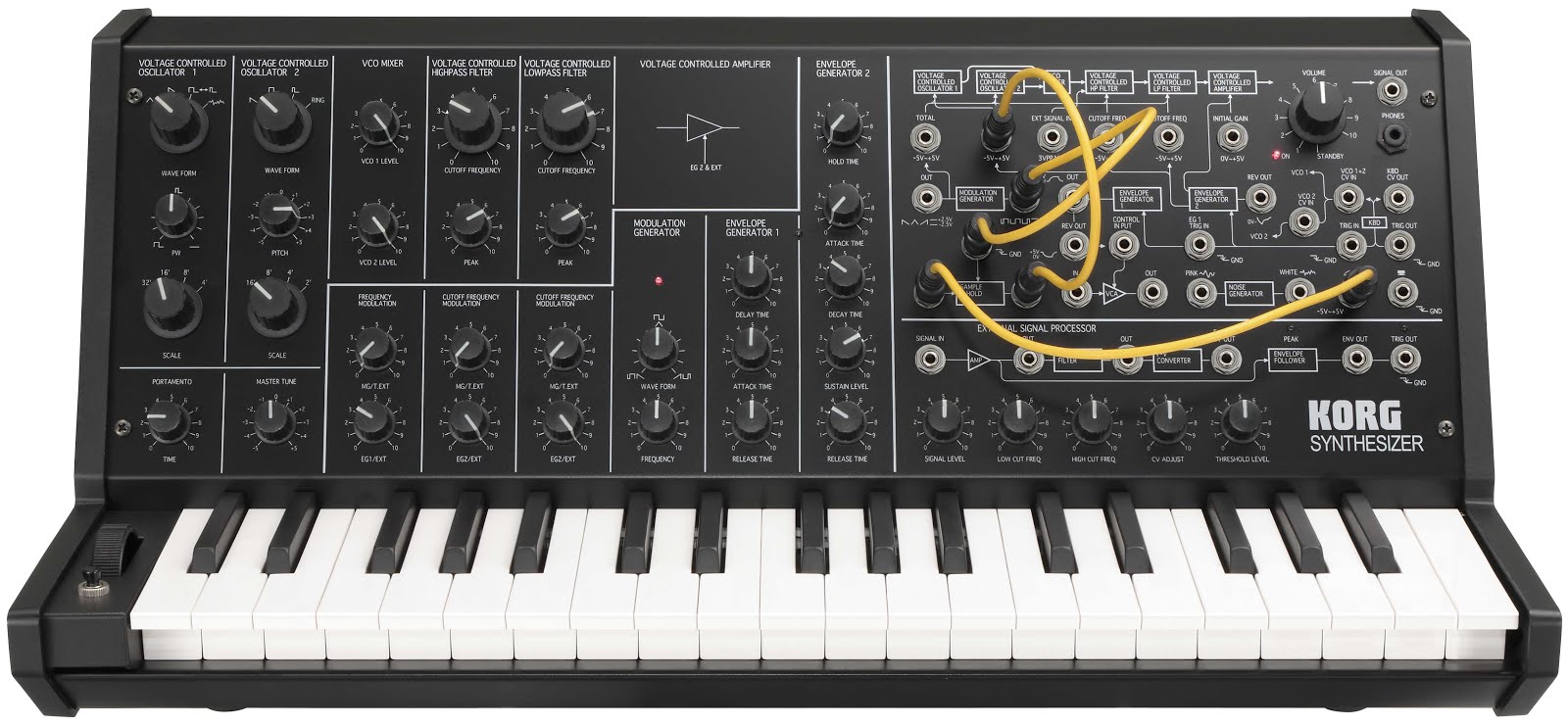
Korg MS-20 Kit Semi Modular Synthesizer: Analog / CV Gate / Midi / USB
Note: Auction links are affiliate links for which the site may be compensated.

via this auction
"Build a real MS-20 with your own hands
Creating an instrument your own hands is the part of the true enjoyment of an analog synthesizer. The MS-20 Kit lets you obtain a real, full-sized MS-20 by assembling it yourself. It goes without saying that, just like the MS-20 mini released in January 2013, the engineers who developed the original MS-20 have overseen this project - ensuring that its historic sound is reproduced with complete fidelity. In addition, the MS-20 Kit provides the filters from both the early and late versions of this classic instrument and it even allows you to switch between them. Today, 36 years after this historic instrument was first unveiled in 1978, the MS-20 returns to its true origin.
A full-size MS-20 that you can assemble yourself
The MS-20 Kit is a kit that lets you obtain a real MS-20 by assembling the parts according to the directions in the owner's manual. Most of the steps are simply a matter of tightening screws or fitting parts together, so you don't need to know about soldering or electronic circuitry. Beyond any doubt, the analog sound generated by the MS-20 that you yourself completed will sound more valuable than that of any other synthesizer.
Unlike the MS-20 mini, the MS-20 Kit is a full-size unit with a standard-sized keyboard, and the plugs are also full sized 1/4" phone plugs.
Two types of filter are provided: both the early and later versions
The original MS-20 used different VCF circuits depending on the date of production. Units produced in the earlier period used a filter noted for its distinctive distortion and self-oscillation, while the filter used in later units was a low-noise design with a more mellow character. Amazingly, this new MS-20 Kit provides both filters. You can switch between the two by moving a jumper pin on the circuit board according to your taste or needs
Overseen by the engineers of the original MS-20; a complete replication of the original analog circuitry
Just like the MS-20 mini, development of the MS-20 Kit was led by the original engineers themselves, who spared no effort to perfectly replicate the circuitry of the original unit. When it was necessary to substitute a part, the engineers made the decision based on their own ears, ensuring that the exact sound of the original unit has been reproduced. In fact, the sound of the MS-20 kit has a somewhat bright and extreme quality to it because its sound is that of an original MS-20 in mint condition at the time it went on sale, before any of the components aged.
2VCO / 2VCF / 2VCA / 2EG / 1LFO structure
The MS-20 kit reproduces the distinctive synthesis of the MS-20; two oscillators with ring modulation, and envelope generators with hold and delay.
External signal processor (ESP) for processing an external signal
The ESP carries on the experimental spirit of MS-20; it allows you to use the pitch or volume of an external audio source to control the synthesizer. For example, you can input an electric guitar and use the MS-20 kit as a guitar synthesizer, or input a mic and use it as a vocal synthesizer.
Extremely flexible patching system
The patching system provided to the right of the panel lets you create complex sounds by plugging-in cables to change the connections between the various units. The possibilities are limited only by the user's imagination; different combinations of the modulation input/output and trigger, sample and hold, and noise generator can produce an incredible variety of sounds. By patching according to the MS-20 flow chart that’s printed on the panel, even the beginner can start taking advantage of these possibilities right away.
Tuesday, January 22, 2013
NAMM 2013: New KORG Mini MS-20 Revealed in German Magazine?

Rough translation:
"Korg is celebrating their 50th company anniversary this year, the MS-20 turns 35. This suggest paying homage to this cult synth. And indeed, on NAMM 2013 Korg presents a "real", fully analog MS-20, just as we know and love it.
Called Mini-MS-20, it is ca. 15% smaller than the original, and sports a MIDI In and a USB MIDI port. This isn't using surplus Legacy cases as some have speculated (which were 20% smaller) but instead individually designed cases, equipped with a specifically developed keybed. The main PCB is more or less euqivalent to the original, including the components selected to be as close to the original as possible. It is not yet known which filter variant has been chosen, although it may be assumed that, just with the Monotron, it will be equivalent to the Korg35 chip, with slight modifications.
BTW, project management were the same engineers who did the originals. As a consequence, the instruments include the original manual, including patch sheets. You don't have to be a seer to expect a golden future for the Mini MS-20. With a suggested price of 600 Euros, this will find many friends, and will make all those happy who couldn't afford a 'real' MS-20 due to their exorbitant 2nd hand prices"
Update: giant size pic of the front. Click here to see it in its full size glory, or click the pic to the left for a smaller but still fairly large image. The image is from KORG.de, here
Update 2: And the product page in German. Googlish:
"MS-20 mini | Monophonic Synthesizer
The MS-20 is reborn! 1978 original circuits come to life
Presented in 1978, the MS-20 monophonic synthesizer, thanks to its rich, robust sound, his powerful, iconic analog filters and flexible patching options to be popular today. The typical sounds of the original MS-20, the Korg MS-20 synthesizer plug-in the Legacy Collection and the iMS-20 app for the iPad, now attracting more than 300,000 users.
Now the sounds of the MS-20, MS-20 are in the mini wakes to new life. The same engineers who developed the 1978 MS-20, today's circuits reproduced faithfully and its physical size reduced to 86% of the original size, without changing the traditional and timeless look of the model or to waive details!
The MS-20 mini fascinated today with absolutely authentic analog synthesizer sounds of his ancestors.
Developer comments
The 50-year anniversary KORG we again engaged in an analogue synth and this effort to create flowing parameter settings that characterize analog synthesizer especially. The original specifications of the MS-20 should remain intact. The developed by us 35 years ago, analog circuits still deliver the same unbeatable, powerful sound, from the lowest bass to the extreme heights. To experience the depth of the MS-20 mini, you have to play it yourself!
Highlights
The MS-20 mini was realized by the engineers of the first MS-20 and used a complete reproduction of the original analog circuit
2VCO / 2VCA / 2VCF / 2EG / 1LFO structure
Self-oscillating high pass / low pass filter with a unique distortion
External signal processor (ESP)
Extremely flexible patching system
Reproduction of the MS20 at 86% of its physical size
Reproduces every detail of the original, down to the packaging, the manual in the original style, the template for the patch panels and patch cables
MIDI IN and USB port"
Update 3: some additional specs:
"Keyboard - control voltage output (exponential) (0 - +8 V)
Keyboard - trigger output (+5 V -> GND)
VCO-2-1 + VCO control voltage input (linear response) (0 - +8 V)
VCO-2 control voltage input (linear response) (0 - +8 V)
Second VCO:
VCO-1 + VCO-2 external frequency control input (OCT / V) (-5 V - +5 V)
Third VCF:
External signal input (max 3 Vp-p.)
External control input for the cutoff frequency of the high-pass filter (2oct / V) (-5 V - +5 V)
External control input for the cutoff frequency of the lowpass filter (2oct / V) (-5 V - +5 V)
4th VCO + VCF:
Total external modulation input (T.EXT) (-5 V - +5 V)
5th VCA:
External control input of the initial gain (0 - +5 V)
6th EC:
EC 1 envelope - Normal output (-5 V - 0 V)
EC 1 envelope - turned output (+5 V - 0 V)
EC EC 1 + 2 trigger input (-> GND)
EC 1 trigger input (-> GND)
EC 2 envelope - turned output (+5 V - 0 V)
7th MG:
Delta output (sawtooth positive - Triangle - Sawtooth inverted) (5 Vp-p)
Square-wave output (pulse width - rectangle - narrow pulse) (0 - +5 V)
8th Noise Generator:
Pink noise output (5 Vp-p)
White Noise output (5 Vp-p)
9th Sample and Hold:
Clock trigger input (-> GND)
Sample signal input (5 Vp-p max.)
S / H output (5 Vp-p max.)
10th Modulation VCA:
Control voltage input (0 - +5 V)
Signal input (-5 V - +5 V)
Signal output (-5 V - +5 V)
11th Game Help Manual:
Control Wheel-output (-5 V <-0 v=""> +5 V)
Non-locking switch output (-> GND)"
Tuesday, December 16, 2014
Introducing the Nodular Desktop Synthesizer - Two Sided Analog Monophonic Semi-Modular Synthesizer
Note: Auction links are affiliate links for which the site may be compensated.

via this auction
Update: the maker/brand name for this synth is ndlr.synths. I created a new channel label for them. We have a new synthesizer manufacturer in town. See second "Update" at the bottom of this post for additional notes on the design.
 via the auction:
"Up for sale: one monophonic analog synthesizer. I've been making analog synthesizers for about 15 years now, but this is the first I am offering up for sale to the 'general public'. I am hoping to make a business out of selling this particular model, and you could be my very first customer.
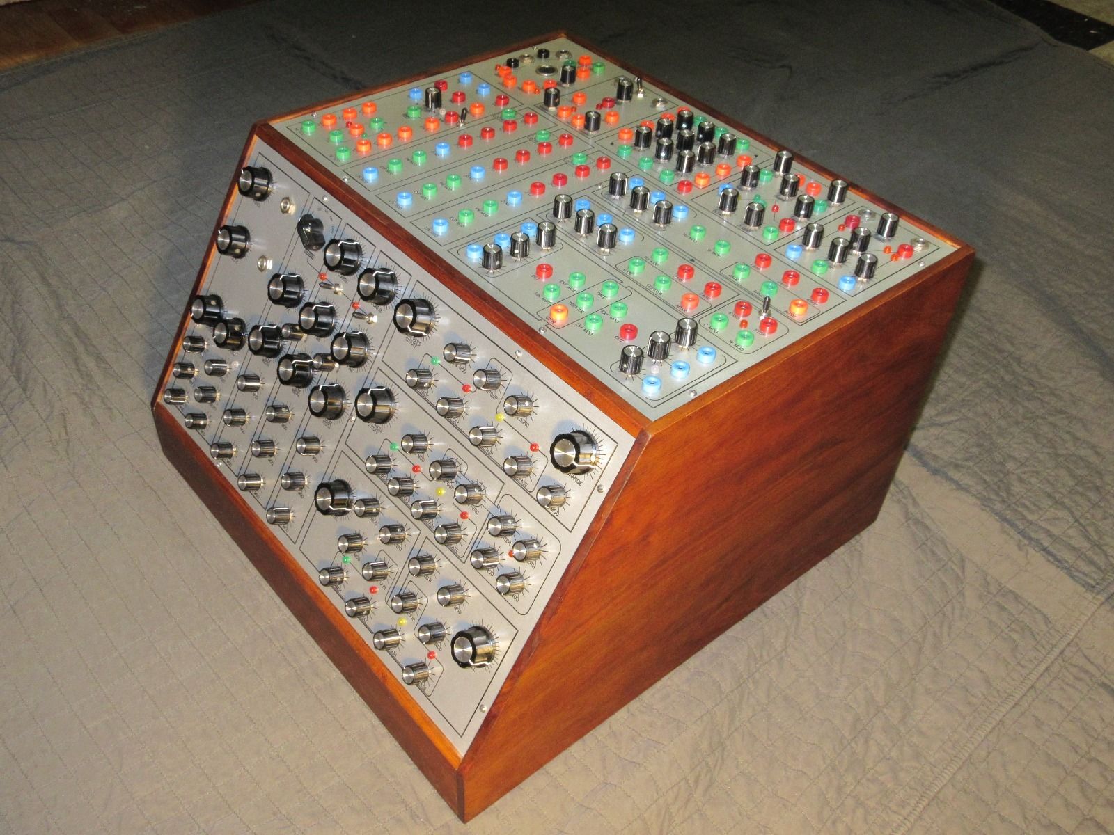
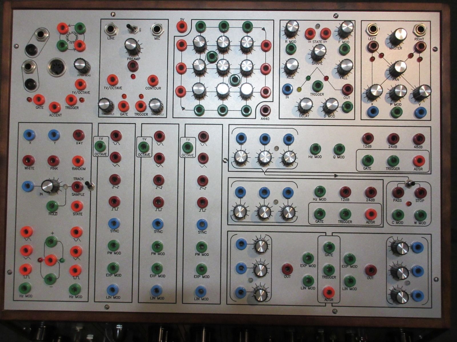
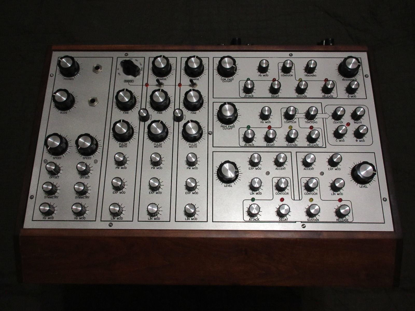
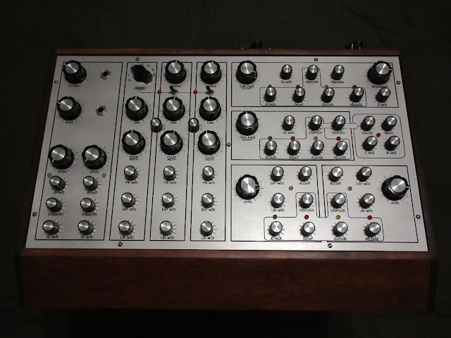 The pictures show the same unit that is up for sale. The cabinet is made from 3/4" natural cherry boards, except for the base, which is made of 3/4" MDF. Both instrument panels are made of 1/8" thick anodized aluminum. The panels have been mechanically engraved and the engravings filled with chemically hardened black enamel paint. The whole unit measures about 18" wide by 18" deep by 12" tall. It weighs about 40 pounds. This is a very well made unit, with sturdy instrument panels that'll last a lifetime.
This synthesizer has its own +15/+10/GND/-10/-15 volt power supply and will only run on 120VAC 60Hz. It consumes about 45 watts of power at full bore.
All the modules in this synthesizer have been designed to work together seamlessly, and all use the same standards: 1 volt per octave, 10 volt peak-to-peak signal voltages, and 5 volt peak-to-peak gate, trigger, and control voltages. All patches are made among the modules via banana jacks. And a few different ways of interfacing to external modules or instruments are offered via 1/4" phone jacks.
A description of the different modules follows:
(1) ring modulator
(1) white and pink noise and random voltage source
(1) sample/track & hold
(1) voltage comparator
(2) low frequency oscillators (LFOs):
(1) headphone amplifier
Both offer voltage controlled frequency, variable offset and symmetry, and sinusoidal, triangular, and pulse wave outputs. By adjusting the speed knob, the frequency can be changed from about 20Hz down to really, really, slow. This range can be extended through voltage control.
(3) voltage controlled oscillators (VCOs):
 All three offer 1 volt per octave frequency control, voltage controlled pulse width modulation, ac-coupled linear frequency control, hard sync, and sine, triangle, sawtooth, and pulse wave outputs. They'll track to within .2% over at least 8 octaves with basically negligible temperature drift once the enclosure is warmed up. And they'll operate from below audio to above audio frequencies.
In addition, the first VCO offers a frequency range switch and fine tuning.
via this auction
Update: the maker/brand name for this synth is ndlr.synths. I created a new channel label for them. We have a new synthesizer manufacturer in town. See second "Update" at the bottom of this post for additional notes on the design.
 via the auction:
"Up for sale: one monophonic analog synthesizer. I've been making analog synthesizers for about 15 years now, but this is the first I am offering up for sale to the 'general public'. I am hoping to make a business out of selling this particular model, and you could be my very first customer.
 The pictures show the same unit that is up for sale. The cabinet is made from 3/4" natural cherry boards, except for the base, which is made of 3/4" MDF. Both instrument panels are made of 1/8" thick anodized aluminum. The panels have been mechanically engraved and the engravings filled with chemically hardened black enamel paint. The whole unit measures about 18" wide by 18" deep by 12" tall. It weighs about 40 pounds. This is a very well made unit, with sturdy instrument panels that'll last a lifetime.
This synthesizer has its own +15/+10/GND/-10/-15 volt power supply and will only run on 120VAC 60Hz. It consumes about 45 watts of power at full bore.
All the modules in this synthesizer have been designed to work together seamlessly, and all use the same standards: 1 volt per octave, 10 volt peak-to-peak signal voltages, and 5 volt peak-to-peak gate, trigger, and control voltages. All patches are made among the modules via banana jacks. And a few different ways of interfacing to external modules or instruments are offered via 1/4" phone jacks.
A description of the different modules follows:
(1) ring modulator
(1) white and pink noise and random voltage source
(1) sample/track & hold
(1) voltage comparator
(2) low frequency oscillators (LFOs):
(1) headphone amplifier
Both offer voltage controlled frequency, variable offset and symmetry, and sinusoidal, triangular, and pulse wave outputs. By adjusting the speed knob, the frequency can be changed from about 20Hz down to really, really, slow. This range can be extended through voltage control.
(3) voltage controlled oscillators (VCOs):
 All three offer 1 volt per octave frequency control, voltage controlled pulse width modulation, ac-coupled linear frequency control, hard sync, and sine, triangle, sawtooth, and pulse wave outputs. They'll track to within .2% over at least 8 octaves with basically negligible temperature drift once the enclosure is warmed up. And they'll operate from below audio to above audio frequencies.
In addition, the first VCO offers a frequency range switch and fine tuning.
Thursday, September 05, 2013
unboxing A-152 addressed T&H/ Switch
Published on Sep 5, 2013
"unboxing A-152 addressed T&H/ Switch
first tweaking with
A149-1 RCV Quantized\Stored Random Voltages
Make noise Function as clock
LDB 1e analog drums
2x monotron-e bass
Pittsburgh sequencer
patch :
LDB 1e analog drums are triggered by a152 Dig out
monotron -e lfo are feed into a149-1
a149 dig rnd outs are feed into a152 sw i/o
function eor and eoc are used as clock for a149 and pittsburg sequencer
pittsburg sequencer two outputs are sent to monotron-e 1v/oct
both monotron-e filters are controlled but it's LFO
function + and - are sent to lfo rest on both monotron-e
a152 T&H controls both monotron-e VCO cv
audio is sent to ableton live and processed with audio damage dr device"
via Doepfer:

Instead of voltage control even clock/reset controlled addressing of the active step is possible. The rising edge of each clock signal causes an advance to the next state. The rising edge of the reset signal resets to step 1.
Basis principles: The sum of the voltages coming from the manual Address control and the CV input define the currently addressed step of the 3 sub-devices. If the module is controlled by clock and reset the control voltage has to remain unchanged as the CV control has priority over the clock/reset control (e.g. simply turn the CV control fully counterclockwise and do not touch the Address control knob).
Sub-device #1 is the bidirectional 8-fold multiplexer (kind of an electronical 8-fold rotary switch). Bidirectional means that it works into both directions like a mechanical rotary switch: the common socket may work as an output that is connected to one of the 8 inputs that are e.g. connected to modulation or audio sources. But the common socket may even function as input. In this case the signal applied to the common socket is output to the currently addressed single socket. The voltage range of the in/outputs to be switched is the full A-100 voltage range -12V....+12V. All A-100 signals can be switched without any restrictions.
LABELS/MORE:
Doepfer,
Erthenvar,
eurorack,
Featured,
Make Noise,
Pittsburgh Modular Confluence,
Video
Monday, May 14, 2012
6HP MIDI TO CV CONVERTER
Note: Auction links are affiliate links for which the site may be compensated.

via this auction
"MIDI TO CV CONVERTERS ARE NOW RELEASED. IT IS SMT BASED. THIS IS FOR DOEPFER COMPATIBLE, EURO FORMAT, MODULAR SYNTHESIZERS.
YOU HAVE TO HAVE A MODULAR CASE FOR YOU TO USE THIS.
A 10 TO 16 PIN HEADER/IDC CABLE AND PANEL SCREWS ARE INCLUDED (M3 TYPE) WITH PURCHASE. THIS FOLLOWS THE -12V GND GND +12V SCHEME. NO EXTERNAL 5V RAIL IS REQUIRED.
MODEL: EURO 6HP MIDI TO CV
CONTROL:
(1) PORTAMENTO KNOB TO DO THE FUNKY WORM OR GANSTER WHISTLE
JACK OUTPUTS:
(2) PITCH CV OUTS
(2) GATE 0-5V OUTS
*BOTH OF THESE OUT PUT AT THE SAME TIME, THIS IS A MONOPHONIC CONVERTER
(1) MIDI CC TO CV OUTPUT
(1) TRIGGER OUT. (THIS IS NOT A CLOCK, IT IS FOR TRIGGERING PERC. MODULES OR ENVELOPES GENERATORS)
(1) GLIDE 0-5V OUT
(1) ACCENT 0-5V OUT
THERE IS ONLY A MIDI INPUT.
(1) LED INDICATES POWER, AND THE OTHER (1) INDICATES MIDI INCOMING NOTES.
YOU CAN CHANGE MIDI CHANNEL 1-16# USING A DIP SWITCH ON THE CIRCUIT PCB."

Monday, October 10, 2011
Blue Lantern Rev4 DIODE VCF
 via this auction
Blue Lantern on eBay
via the listing: "Here is my new Rev4 DIODE VCF. I also had Pro Panels made. This filter has a 10-stage Diode Ladder. It sounds so sweet! This is the best Diode Ladder VCF so far, and to top it off 6hp!!
These were built by me and are new. I tested each one myself and they are good to go. This auction price is Per Unit Cost. So (1) Diode VCF is $125.00
This is a small run of around 20 units. Get'm while there hot. They will probably go fast so don't wait to long.
Specs:
--------------------------------------------
(1) DIRECT CV Input
(1) FM Bi-polar Attenu-Inverter (+&- CV Input)
(1) FILTER OUTPUT
(1) EACH--HP/LP/BP inputs
There is a trim pot to adjust how much screech you want on the Rez pot. You can make it Squelchy or tame it down.
----I include a 10 PIN to 16 PIN IDC ribbon cable for you to connect to your Euro Compatible Modular Case. I use the Red Stripe is (-12v) standard. Please pay attention when connecting the unit yourself. If connected wrong you will fry the IC chips and see smoke.
The standard is as follows: -12v GND GND GND +12v. On a Doefper system the red strip usually will be on the bottom. On my modules the red stripe is on the top. All I did was rotate the standard connector on my PCB modules.
The panel is made of a High Grade PCB material with White Silk-screening done by a Pro PCB manufacturer. I had to include these costs on this newer unit."
DEMO OF NEW DIODE VCF REV4 by Blue Lantern


Tuesday, May 31, 2011
EURO-FORMAT MIDI -2- CV CONVERTER
 via this auction
"THIS MODULE IS USED TO INTERFACE MIDI KEYBOARDS, OR YOUR COMPUTER MIDI SEQUENCER. IT IS BASED ON THE 1V/OCT EXPO. STANDARD.
THE PANEL IS 12HP WIDE.
THE SPECS:
(2) PITCH CV OUTS
(2) GATE OUTS (~5V) (+5V ON, 0V OFF)
(1) TRIGGER OUT
(1) CC #100 CV OUT
(1) ACCENT (~5V) TRIGGER OUT
(1) SLIDE (~5V) TRIGGER OUT
 THERE IS PORTAMENTO ON BOTH PITCH CV OUTS. IT IS CONTROLLED BY KNOB. THERE IS A BLACK SOFT RUBBER KNOB WITH GREEN LINE.
THERE IS A GREEN LED TO SHOW MIDI NOTE ACTIVITY.
BY DEFAULT IT IS SET TO MIDI CHANNEL 1 (ALL DIP-SWITCHES OFF), WITH A DIP SWITCH ON, ONE COULD CHANGE THE MIDI CHANNEL.
ON THE IDC CABLE, THE STRIP IS -12V. I FOLLOW THE DOEPFER POWER SCHEME OF -12V GND GND GND +12V"

Friday, November 18, 2011
Blue Lantern NOISE GENERATOR AND WAVE FOLDER

via this auction
See the seller's other items for more.
"Introducing the next lineup of module to get the Pro Panel treatment. It is the tried and true Analog Noise Generator, but the design was so slick I was able to fit a Lock Hart Wave Folder & Gate to Trigger converter. The entire back PCB area is less then 2" (1.5") in depth. It is made with SMT parts.
This is for Euro Format Modular Synth Cases. The user is to install this module themselves using a IDC cable which is included.
THE UNIT COMES WITH A 10 PIN TO 16 PIN IDC CABLE.
POWER SPECS: PLEASE READ THIS AND YOU SHALL NOT BE SORRY! THE MODULE CONFORMS TO THE NEWER DOEPFER POWER LAYOUT SCHEME. ON MY MODULES RED LINE IS (-12V) AND STARTS AT THE TOP.
THE SEQUENCE IS -12V/GND/GND/GND/+12V. SO +12V IS AT THE BOTTOM ON MY MODULES. ALL I DID WAS ROTATE THE DOEPFER STANDARD. THE MODULES COME SHIPPED WITH THE CABLE CONNECTED CORRECTLY. ALL YOU HAVE TO DO IS CONNECT THE RED STRIP TO YOUR -12V END ON YOUR CASE WHICH IF IT FOLLOWS MOST WILL BE AT THE BOTTOM. THERE IS A SILKSCREEN ON THE MODULE TO SEE THE LAYOUT ON THE HEADER ALSO.
THERE ARE SAFETY PTC RESETTABLE FUSES INSTALL ON THE MODULE THAT WILL OPEN THE CIRCUIT IF CONNECTED WRONG. BUT IT IS GOOD PRACTICE TO JUST READ DIRECTIONS. FEEL FREE TO EMAIL ME IF YOU JUST ARE NOT SURE HOW TO CONNECT THE MODULE TO THE EURO CASE FORMAT POWER STRIP.
MODULE
SPECS:
Width--4HP
Circuit 1: NOISE GENERATOR: White Noise, High Pass White Noise, Low Pass White Noise, Red Noise. There is a Trimmer on the PCB that will adjust the Loudness of the core Noise generator. 100% Analog. ALL OUTPUTS.
Circuit 2: Lock Hart Wave Folder: There is (1) Input, (1) Double Pulse Output, (1) Folded Output. In order to control the actual folding, an Attenuator is needed right before the Input Chain in your Patching. Sine or Triangle Waves work best here, but you are free to Experiment.
Circuit 3: Gate to Trigger Converter. This will make a Gate into a short Pulse. Useful for triggering Drum Synths. Again you can also experiment with feeding in slow LFO wave forms and hearing the Audio Result.
All that in 4HP!"

Monday, March 16, 2009
Roland TR77 Rhythm Machine
 via this auction
"Roland TR77 Rhythm synth.
The Roland Rhythm 77 drum machine was Roland's first product (formerly Ace electronics) - released in 1972. It is actually an updated and relabelled Rhythm Ace FR-8L.
It was one of a trio of drum machines released by Roland that year, offering features intermediate between those of Rhythm 33 (TR-33) and Rhythm 55 (TR-55).
It comes in a flat wooden case with a metal base and has a holding for scorebooks - was dedicated to put at top of an organ for rhythm accompaniment.
General Product Information:
Contents
* 1 Rhythms:
* 2 Instruments:
* 3 Some technical inside:
* 4 External Sync
Rhythms:
· Latin: rhumba, beguine, cha-cha, mambo, samba 1&2, bossa nova, baion, bolero, tango
· Rock: rock'n'roll 1&2, slow rock, ballad, western, march, jazz waltz, waltz, cancel
· 2beat & 4beat: bass drum, snare, fox trot, swing, parade, shuffle
Instruments:
Bass drum, snare drum, lo conga, low bongo, high bongo, rim shot, maracas, high hat, cymbal, tambourine, guiro, cow bell. Rim are used for metronome, too.
has a little mixer for: bass drum, snare drum, guiro, high hats.
has a tempo & volume fader; and a fade-out option : for start there's no button, it's a finger-sensitive touch-bar, supports double tempo.
the power switch is not a primary AC-switch.
Some technical inside:
There's no IC inside - only one VCA...
Left: transformer, rectifier, softstart.
Mid: master clock, 5 dividers, reloop & down-beat LED, diode matrix.
The 1st divider is connected to the tempo-up switsch for a 1:1 or 1:2 ratio, the 2nd ones for switching between the 4/4 and 3/4 clock - 1:2 or 1:3 ratio.
Right: the voice board, mixer & output stage. BD, LC, LB, HB, rim are passive circuits.
Bottom: the rhythm switches...
External Sync
There's a little possibility to use din-sync on this device.
Logic board: leftest transistor, on its right the base resistor, solder on lower pin the clock line. For start/stop - its like a pedal switch - just put a transistor serial into the male connector: gnd=emitter, top=collector, base=start/stop line.
Works best at 8 ppm clock, up-tempo off for best results. On up-tempo on the guiro & tambourine it sounds bad as they have a 2nd trigger input which they get from the 1st divider."
Monday, September 12, 2011
Blue Lantern VCO

via this auction
"THIS VCO HAS THE BASICS
THE SPECS:
WAVES: SAW(RAMP),TRIANGLE, AND SQUARE WAVE. SAW AND SQUARE IS SELECTED BY SWITCH.
-(2) 1V/OCT CV INPUTS
-(1) LINEAR CV INPUT
-(1) PULSE WIDTH MOD INPUT
-(1) HARD SYNC INPUT
POWER CONNECTOR: NEWER 10 PIN DOEPFER TYPE (-12V GND GND GND +12). THE STRIP LINE ON THE RIBBON IS -12V
KNOBS: TUNE, FINE TUNE, PULSE WIDTH FOR THE SQUARE WAVE.
FREQUENCY RANGE FROM 0.1Hz TO ULTRASONIC 20KHz"
Wednesday, January 06, 2010
Elektron machinedrum SPS 1 UW triggering boss SYB 5 bass synthesizer pedal
YouTube via helefthandedheroes
"Elektron Machinedrum SPS-1 UW GND-SN machine triggering BOSS SYB-5 bass synthesizer pedal. The GND-SN machine routed to an individual out to Boss SYB-5 to INP-EA machine for filtering.
Just realized that the first few minutes had that stupid delay on.
All other sounds are machinedrum GND-SN sine machines!
At the time of recording I was first time trying out the pedal, only discovering the possibilities.
The video is to show what kind of sounds you can get triggering the SYB-5 with a GND-SN and was put into an electronic context.
Not a musical statement.
The video was shot with a Nokia N95, the sound quality is far from amazing.
SLEEP LESS :: LOVE MORE"
Saturday, July 25, 2009
Elektron Machinedrum driving Korg MS-10
YouTube via darenager
"Using the Machinedrum to drive a Korg MS10
1. Set up a GND-IMP machine and a GND-SIN machine, in global setting route each of these to their own output - I used E and F in this example.
2. For the GND-IMP machine set it UP to 0, UVAL to 0, DOWN to 64 and DVAL to 127, set the track level and volume to maximum. This will be your trigger pulse, so connect a lead from the output you assigned this machine to into the MS10 trigger input. (output E in my case)
3. For the GND-SIN set it at maximum level and volume, also turn DIST in the routing page fully up (127), set the RAMP and RDEC to zero. This will be your pitch control, route it from its output on the MD you selected earlier into the VCO CV input. (output F in my case)
4. Select accent track and set it to max for all steps and all tracks, it is important that you do this or it won't work as the accent boosts the juice a bit.
5. Program some triggers for the IMP machine, then place triggers on the same steps for the SIN machine, using parameter locks on the PTCH control you can change the pitch played by the MS10, experiment with different envelope settings on the MS and different triggers for the IMP and SIN machines.
As you can tell from the video, there are a few limitations with this technique, first the pitch is not linear and does not act as anything like normal scaling, second on the MS10 you get some bleed though of the SIN sound. If you are electronically minded it should be feasable to build a little circuit to boost the CV output a bit.
You can also route the SIN to the V/OCT input or the filter CV input on the MS10, just remember to set the ENV/EXT knob on the VCO or VCF to a high setting or you won't get as much modulation. This can yield some interesting sounds, have fun and experiment. If you use the V/OCT input you can change the base pitch by playing the keyboard on the MS10.
This technique can also work with other synths or devices with CV inputs with varying degrees of success. Also you can use the LFO on the pitch of the SIN machine for some weird fx.
I think that is everything, if I have left anything out let me know.
Any questions let me know.
Cheers
Daren"
Wednesday, November 18, 2009
Elektron Machinedrum triggering BOSS SYB-5 Bass Synthesizer pedal
Elektron Machinedrum triggering BOSS SYB-5 Bass Synthesizer pedal from lefthandedheroes on Vimeo.
"Elektron Machinedrum SPS-1 UW GND-SN machine triggering BOSS SYB-5 bass synthesizer pedal. The GND-SN machine routed to an individual out -> Boss SYB-5 -> INP-EA machine for filtering.
Just realized that the first few minutes had that stupid delay on.
All other sounds are machinedrum GND-SN sine machines!
At the time of recording I was first time trying out the pedal, only discovering the possibilities.
The video is to show what kind of sounds you can get triggering the SYB-5 with a GND-SN and was put into an electronic context.
Not a musical statement.
The video was shot with a Nokia N95, the sound quality is far from amazing.
SLEEP LESS :: LOVE MORE"
Wednesday, August 03, 2011
Monotribe has MIDI out hidden inside
YouTube Uploaded by Gameboygenius on Aug 3, 2011
"Someone suggested the "serial" connector on the Korg monotribe might spit out MIDI signals. That person was right!
Discussion on Muff Wiggler forums: http://www.muffwiggler.com/forum/viewtopic.php?p=531711#531711"
via nitro2k01:
"CONFIRMED! It is actually spitting out proper MIDI on the serial line! It gives you the following:
Note data.
MIDI sync, incl. start and stop messages.
Automation data for all of the LFO settings (both the knobs and the switches) and the EG shape. This suggests that the LFO and envelope may be created in software.
I have not yet hooked up an optocoupler and fed the thing MIDI from the other end, but I will. Shorting the serial out and serial in ports glitches the thing, so it most probably is capable of receiving MIDI.
Here's the pinout for the pin connector marked serial on the board.
Code:
CN12 MCU
1 Pin 20 PH0, TB0IN0, /BOOT
2 Pin 12 RXD0
3 Pin 11 TXD0
4 Pin 9 Vdd (3 V)
5 Gnd
6 Pin 29 PF6/SCK1
I believe this header was intended for factory programming of the firmware. When pin 1 is held low, the MCU enter a special programming mode, according to the datasheet. Pin 6 goes is routed up to somwhere near the power switch and is probably used to detect when a unit is turned on to begin the programming.
CN13 (which comes with no connector attached) would be used for debugging, but it is likely that debugging is disabled so you can't dump the firmware etc. Still haven't looked into that. (I don't have JTAG tools readily available, so...)
But what we're interested in is pins 2-5. Pin 2 is for receiving MIDI. Pin 3 is where MIDI comes out. If you're going to try to add an optocoupler, you'll also need Gnd and Vdd.
MIDI is a current loop protocol, so 3.3 V is no problem for standard MIDI gear given that you adjust the output resistors accordingly. Following the standard MIDI convention, I connected 3.3V and the output as usual, but replaced the usual 220 ohm resistors with 150 ohm ones. Works well enough.
I also got an idea: If the monotribe can receive MIDI, that may open up the possibility of throwing the internal oscillator out the window and using the it as a self-tuning MIDI CV interface for modulars. However, I've found that at least my monotribe tracks badly and sometimes drifts a little. This is especially obvious when comparing it to a well-tuned computer playing the same MIDI notes. Also, it's using just 5V internally for the analogue part (3.3V for the digital) and the CV range may be even less, so perhaps it wouldnn't be of much use for 1 V/oct systems.
More to come..."
Sunday, March 26, 2023

Monday, October 07, 2013
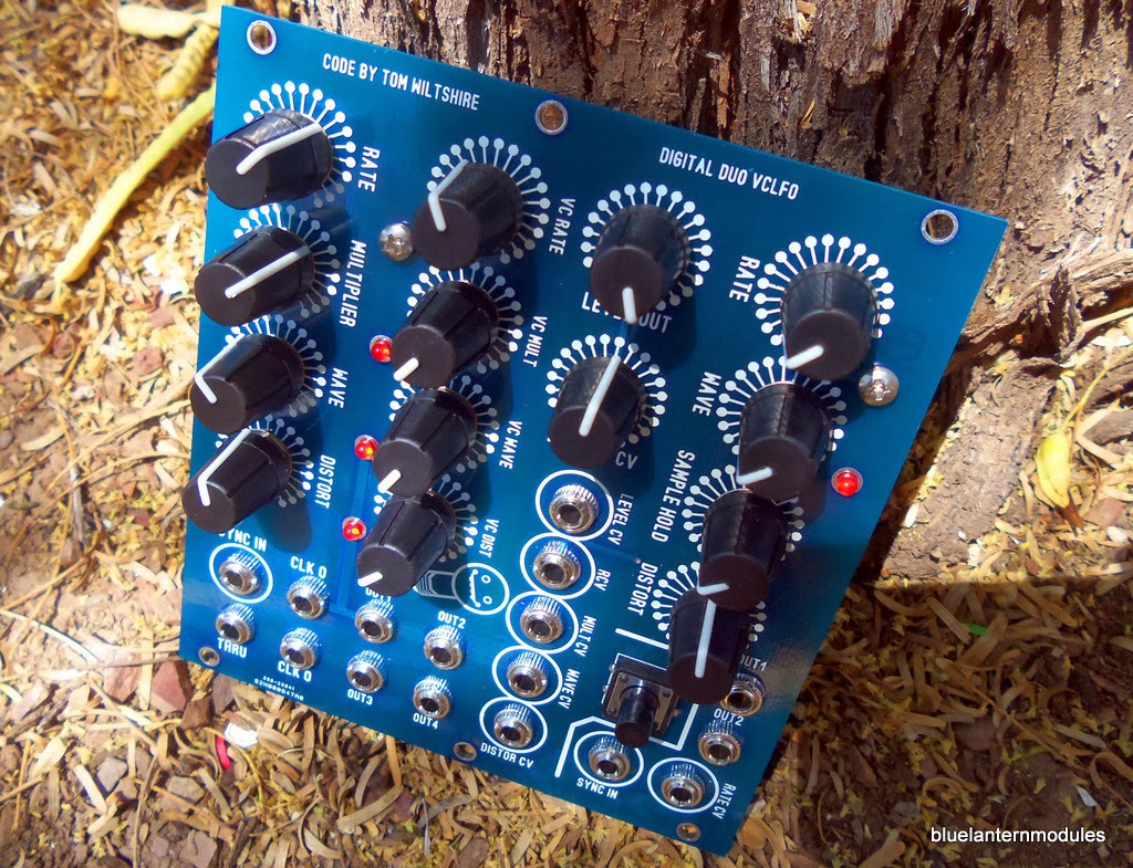
Blue Lantern Modules - DUO DIGITAL VCLFO Eurorack format
Note: Auction links are affiliate links for which the site may be compensated.

via this auction - learn how to sell on eBay here
See the seller's other items for more.
"The price is below the intended retail price. So save some $$$$$ before the final release. I have (4) of these to sell.
This is the updated module that is to replace the BLM 'White VCLFO'. I decided to include both of Tom Wiltshire's digital lfo's on one module. I feel they both compliment each other. I am giving you a nice price before the officially release of this product. This is a small run of 4 units. I kept (1) for myself and am selling the rest of them. The sale of these is to raise money and pay for a bigger run.
M3 panels screws, and 10pin to 16 pin IDC cable is included.
Some notes about Blue Lantern Modules: I like to use -12v gnd gnd gnd +12v on the actual module power connector. I don't use the rest of the doepfer pins: 5v, gate, cv. I use keyed headers. So the way I crimp the IDC cable I have the red strip facing up on the module itself. Red strip on a Blue Lantern Module product means -12v...

Monday, February 14, 2011
TinySID on a 16 bit PIC
YouTube via markusgritsch | February 14, 2011 |
Layla at 1:00
"Ater successfully getting the TinySID library running on a PIC32 [1] some time ago, I recently wondered, if the 16 bit MCUs from Microchip would also be fast enough to run the code. It turned out, that they are, at least the 40 MIPS models (PIC24H and dsPIC33F).
A big hurdle is the (compared to the PIC32MX) small RAM on these chips. Since the SID tune must be loaded into RAM, only some small tunes will fit into the 8 kB of the MCU used on the Web Platform [2] I had at hand.
However, the source code [3] and binary [4] are available from Google Code. The PWM output is on IO7, and IO8 is used to switch the tune when pulled to GND.
Have fun,
Markus
[1] http://www.youtube.com/watch?v=ZNu0-M...
[2] http://dangerousprototypes.com/docs/W...
[3] http://code.google.com/p/dangerous-pr...
[4] http://code.google.com/p/dangerous-pr..."
Active links on YouTube
Thursday, November 24, 2022
Speak & Glitch GND-1 | Circuit Bent Speak Chip Synthesizer
video upload by Shirato_Noise
"This compact synthesizer seems to contain every imaginable Speak Chip-based bent sound we can imagine. I have great appreciation and respect for Richard for making this instrument a reality."
NEXT PAGE
HOME


© Matrixsynth - All posts are presented here for informative, historical and educative purposes as applicable within fair use.
MATRIXSYNTH is supported by affiliate links that use cookies to track clickthroughs and sales. See the privacy policy for details.
MATRIXSYNTH - EVERYTHING SYNTH
© Matrixsynth - All posts are presented here for informative, historical and educative purposes as applicable within fair use.
MATRIXSYNTH is supported by affiliate links that use cookies to track clickthroughs and sales. See the privacy policy for details.
MATRIXSYNTH - EVERYTHING SYNTH


