Showing posts sorted by date for query Radical Frequencies. Sort by relevance Show all posts
Showing posts sorted by date for query Radical Frequencies. Sort by relevance Show all posts
Thursday, March 11, 2021
AD Multi VCO Krell style patch
video by Radical Frequencies Modular
"AD Multi Vco clip showing one of the waveforms the triangle pulse in a krell style patch:
I use 2 RF VC Adsr in (one is the master clock) , one RF lucky voltages and a beatstep pro sequencer .
Later in the patch I use alpha vco from dpvco to sync the ADMVCO and to modulate the linear fm with the AC input choice .The sound is fat and alive while it is physical sounding !The adsr makes amplitude modulation to the final vca.
The master clock adsr that modulates the triangle adding harmonics to the wave so I don’t use any filter to this patch ! Incredible feature for making sound only from vco direct to a vca :)"
Wednesday, January 13, 2021
Radical Frequencies Modular
"Happy New Year my modular friends with a Radical Frequencies modular 132bpm Psychedelic Techno jam! Patch: The Fm lead is a pulse wave from a RF dpvco with internal pwm and linear fm going into RF Scota vcf (alpha filter only) using band pass output and voltage controlled by RF vc adsr and lucky voltages randomizes the decay times . The Bass is another dpvco with 2 detuned saw waves into RF 12db multi vcf. The Drums are from iPad Launchpad . All sequences are trigged by Beatstep Pro that takes clock from iPad . All sounds are multi recorded into daw though apogee and mytek converters and the lead is mixed with reverb & delay. https://www.radicalfrequencies.com/in..."
Note the player above is a playlist of all videos by Radical Frequencies Modular starting with the New Years jam.
Spotted on discchord
Sunday, July 07, 2019
Radical Frequencies -Waveshaper/ Sub oscillator
Published on Jul 7, 2019 Dziam Bass
"I have today a small demo of the module from Radical Frequencies which recently came to us from Greece.
This is Waveshaper and Sub oscillator so we recorded a little fun with Shape I Range, but also when we add the oscillator to the Sub which dramatically strengthens the sound. Used on one VCO Minimod -Vintage Transistor Core VCO from AJH Synth.
This module is a 100% fully handmade and inspirational synthesizer from the '70s, it is the domain of Radical Frequencies which we appreciate very much."

via Radical Frequencies
"100% handmade through hole Waveshaper and Suboscillator in one module with discrete transistor core circuit.
The Radical Frequencies Waveshaper-Suboscillator is a two input wavefolderr with shape
and range controls that allow for timbre manipulation, in conjunction with the input amount on each channel.
The module is one big organic block of harmonic generation.
All controls are interconnected and have a great impact on the final out.
CV control if offered and controls the level of both audio inputs.
A sub oscillator circuit is included, offering switchable -1 and -2 octaves.
The square wave has an inverted output too.
An attenuator is included, providing mixing capabilities of the sub out.
When no sub out is desired to be present in the mix out, the sub osc audio input should have nothing patched in."
Wednesday, January 02, 2019
WMD SYNCHRODYNE - A demystifying in-depth demo
Published on Jan 2, 2019 WMDevices
"What is the most insane sounding eurorack module ever? How can I make crazy techno sounds and ambient textures with the same module? Do I really need a modular synth? Can't I just make all of the same sounds a hardware synthesizer can with my VSTs? What is the Synchrodyne and what can it do for my music?
If you are asking yourself these questions, you may enjoy this video. If you've heard of the Synchrodyne and have no idea what it is, you may enjoy this video. If you are looking for ways to expand your sonic palette to unheard of realms, you might enjoy this video.
If you like listening to electronic music that doesn't sound like the inside of a Forever 21, you could very well enjoy this video.
The Synchrodyne is a filter for the Eurorack format of modular synthesizers. A crazy cool filter with tons and tons of sonic possibilities as well as the capability to be it's own standalone voice. What makes this filter unique is that it uses a Switched Capacitor design that uses capacitors and switches, controlled by a high speed clock to filter incoming audio.
This module has it's own internal clock VCO that is capable of reaching supersonic frequencies, making it perfect for clocking the filter while processing external sources. However, we really wanted to be able to use this VCO as our main sound source instead of requiring and external oscillator. What we came up with was to use a PLL (Phase Locked Loop) circuit with some Clock Multipliers and Dividers to track our oscillator's frequency while it is in the audible range with the ability to be multiplied to the supersonic frequency necessary for clocking the filter. The PLL circuit made for an radical, very unique sound that we had never hear before.
In this video, Alex talks through each section of the Synchrodyne while providing high quality audio examples of what this module is capable of as well as real world uses in live performance and in the studio. This video is more focused on creating house, techno, and dance music with the Synchrodyne. A showcase of it's ambient sounds will come in another video.
Enjoy!"
Wednesday, December 20, 2017
Radical Frequencies Dual Precision Oscillator (LMS EE)
Published on Dec 20, 2017 Learning Modular
Playlist:
1.Radical Frequencies DPVCO 1/4: overview (LMS Eurorack Expansion Project)
The Radical Frequencies Dual Precision VCO features a pair of oscillator with excellent tracking (6 octaves is the claim) that go from slow LFOs up into very high frequencies. It offers both linear and exponential FM, pulse width modulation up into the audible range, and soft sync. The advantage of having two oscillators behind one panel is that it features a lot of intelligent normalization, as well as jacks with attenuators to plug in external signals. This first movie features a demo arpeggio showing off the major features, and then demonstrates each of its waveforms and major sections:
0:00 demo
2:51 specs & background
4:07 tuning range
5:13 pulse width modulation
5:58 square wave
7:06 sawtooth
7:45 triangle
8:35 sine
9:17 (repatching & retuning)
10:00 soft sync
11:06 preview of next two movies
For more details about using the Dual Precision VCO (as well as other modules I’ve made videos for), I encourage you to join the Learning Modular Patreon Tribe: https://www.patreon.com/LearningModular. For more on the Learning Modular Synthesis Eurorack Expansion Project for those exploring what module to add to their system next, visit http://learningmodular.com/eurorack-e...
2. Radical Frequencies DPVCO 2/4: static FM (LMS Eurorack Expansion Project)
In this second movie on the Radical Frequencies Dual Precision VCO, I focus on dialing in frequency modulation using the front panel controls, without any external envelopes or VCAs. If you’d like a demo of the differences between linear and exponential FM – and what things like waveshape and offset mean to the resulting tuning – this movie is for you. Near the end, I also demonstrate pulse width modulation, including the great sound you get when you modulate it with an audio oscillator as well. Here is a breakdown of what’s covered when in this movie:
0:00 overview
0:46 triangle versus sine for carrier
1:04 entrainment
1:50 linear FM
6:49 exponential FM
12:11 pulse width modulation
13:18 combining techniques
13:51 cross-modulation
3. Radical Frequencies DPVCO 3/4: dynamic FM (LMS Eurorack Expansion Project)
In this third movie on the Radical Frequencies Dual Precision VCO, I focus on dynamic frequency modulation where I use an external envelope and VCA to dynamically change the FM depth for each note played. I compare linear versus exponential FM, showing where linear is good for tonal and sustained sounds while exponential is good at percussion as well as adding pluck or strike to the start of each note. Here is a breakdown of what’s covered when in this movie:
0:00 overview
0:38 the basic patch
1:20 dialing in enveloped linear FM
3:45 enveloping exponential FM
4:54 FM percussion sounds
5:47 adding an FM strike or pluck
7:49 layering techniques
4. Radical Frequencies DPVCO 4/4: soft sync (LMS Eurorack Expansion Project)
In this fourth and final movie on the Radical Frequencies Dual Precision VCO, I focus on its soft sync function. I explain how sync works, compare soft and hard sync, and play around with creating alternate timbres and glitchy enveloped sounds using soft sync. Here is a breakdown of the final movie:
0:00 an overview of sync
2:28 tuning the master lower than the slave
3:26 tuning the master higher than the slave
5:01 soft sync variations
6:54 enveloping the slave’s pitch (including hard sync comparison)
9:18 layering techniques
Friday, December 15, 2017
Radical Frequencies Dual Precison VCO: teaser
Published on Dec 15, 2017 Learning Modular
"The intro jam to a four movie set I'm creating on the Radical Frequencies Dual Precision VCO, showing off its linear and exponential FM as well as frequency-rate modulation of its pulse width. This is one bad-ass dual oscillator."
http://bit.ly/LearningModular
Friday, November 17, 2017
Analogue Solutions Mr Hyde and Dr Strangelove synthBlocks Signal Processors Now Available

"AS announces availability of Mr Hyde and Dr Strangelove synthBlocks signal processors
KINGSWINFORD, UK: British boutique electronic instruments innovator Analogue Solutions is proud to announce availability of Mr Hyde and Dr Strangelove — introducing its synthBlocks series of small and affordable desktop signal processors with two tantalisingly-named new products squarely aimed at laptop and audio plug-ins-focused digital musicians wishing to apply analogue, hands-on hardware processing to their sometimes sterile-sounding computer- based creations — as of November 17…
The synthBlocks series represents an all-new range of small and affordable desktop signal processors produced by British boutique electronic instruments innovator Analogue Solutions, an acclaimed company with over 24 years of designing serious-sounding synthesizers featuring fully-analogue audio paths with analogue LFOs (Low Frequency Oscillators) and EGs (Envelope Generators) to its notable name. Similarly, synthBlocks are all-analogue affairs — albeit with some lo-fi digital effects thrown in for good (musical) measure. Menus and software are all eschewed in favour of a hardy hardware approach. As such, synthBlocks are squarely aimed at laptop and audio plug-ins-focused digital musicians wishing to apply analogue, hands-on hardware processing to their sometimes sterile-sounding computer-based creations. Cue simply plugging the synthBlocks in question into an audio interface’s I/O connections, then routing drums, synths, vocals, or whatever out of the DAW (Digital Audio Workstation) and through the transistors and op-amps of the synthBlocks and recording the results back into the DAW. Something similar can be achieved by connecting the synthBlocks to the auxiliary buss of a mixing console — just like any other effects processor. Whatever the workflow, turning the dials and flicking the switches by hand of course changes the sound in realtime — often with radical results. Results of course can be radically different — depending on which of the two available synthBlocks are applied to any given sound signal.
Many might have heard of Mr Edward Hyde, an abominable alternative personality of Dr Henry Jekyll, a fictional character in Robert Louis Stevenson's Strange Case of Dr Jekyll and Mr Hyde gothic novella first published in 1886. However, hearing Analogue Solutions’ Mr Hyde in the here and now is something else entirely! As announced, Mr Hyde was the first out of the starting blocks in its synthBlocks series as an analogue filter effects box bringing subtle to extreme filtering and modulation effects to the analogue processing production table. To further aid ease of use, Mr Hyde has quarter-inch input and output jacks on its rear, so can be connected straight to an audio interface or mixer without the need for adaptors. The topside of its distinctive blood-red panel features minijack sockets to patch with a semi-modular synth, such as Analogue Solutions’ relatively recently released Fusebox — an aptly-named, three-VCO (Voltage- Controlled Oscillator) true analogue monophonic synthesizer that favourably fuses the company’s characterful vintage sound with an advanced choice of modulation and melodic possibilities (in a beautifully-built box); ever-popular Eurorack small-format modular systems; or other modular systems.
Friday, August 19, 2016
Synthrotek AstroNoise Eurorack Mod
Published on Aug 18, 2016
"Learn how to mod your AstroNoise here: http://www.synthrotek.com/kit-assembl...
The AstroNoise is a massive vintage video game-inspired noise-making machine! Shape the galactic frequencies with 4 onboard controls. The "Oscillator Rate" controls the master frequency. The two LFOs and the LFO pitch modulate that frequency and together allow you to make rhythms, video game motorcycle sounds and more.
The AstroNoise whets your appetite further by letting you choose between 3 different radical vintage tones. The adventurous user can use it to make beats, lead lines and noise swashes by connecting other devices into the LFO input and the Control Voltage input (optional). The fun doesn't end after building the circuit! Take your creative skills further by designing your own custom enclosure out of an old cigar box, lunch box, doll head, etc!
Features:
- Tone Select Switch lets you choose between three classic sounds: bleeps and bloops, 8bit explosions and razor-edge squares
- Oscillator Rate Control ("Rate" on the PCB) changes the master frequency and rate
- LFO Rate 1 Control (OSC1)
- LFO Rate 2 Control (OSC2)
- LFO Pitch Control (OSC_LVL)
- Volume Control
- Oscillator On/Off switch (turns off LFO Rate 1/OSC1 and LFO Pitch/OSC_LVL)
- LFO Input (OSC_IN): use for external control of LFO Rate 1 with an input of 1-150 Hz
- Control Voltage (CV) input (disables LFOs)
- Power on/off switch
- 9V DC jack and battery clip"
Friday, March 11, 2016
NYZ DRN4 DECLASSIFIED
Exclusive mix on SoundCloud:
Tracklist:
1. NYZ_FMMGKSQ_43t
2. ISR_16x16_WCM
3. CSN [excerpt 2 mono]
4. SWI_r170_16x32x32_B
5. SWI_FM1#16
6. NYZ-1_1#08_A [finite downsized]
7.CSN1 [excerpt 1 mono]
Be sure to see the MATRIXSYNTH exclusive further below!
FM EXPLORATIONS AND MICROTONAL DRONES FROM NYZ (AKA DAVE NOYZE, DAVID BURRASTON, NOYZELAB, BRYEN TELKO)
This is the first release by NYZ and is a superb musical collection of research areas classified to internal Noyzelab operations. Not even .MEDS label were informed of the secret processes underlying its creation, excepting that we know it involved Frequency Modulation (FM) synthesis! We have not been given any information regarding when this work was recorded, but we suspect the material spans at least a decade of David's FM algorithm research on numerous synthesizers, as well his own custom built ear deceiving gear...
According to one reviewer of David's previous musical output he "gleefully disrupts just about every standard convention of musical form you could think of, including those of so-called experimental musics."
Other reviewers have written that :
"His music is a bizarre, yet compelling journey investigating the outer realms of music generated on ancient & contemporary machines." "It's strikingly original audio that doesn't really sound like anything else I can think of." "Utterly sublime. So there you go, a life-affirming slab of mind-altering sound to reawaken you to the terrifying possibilities of creation."
"absolutely wreaks havoc" wrote Keith Fullerton Whitman on reviewing David's last release T. H. Cycle cassette on Important Records/Cassauna .
Cassette releases April 1, 2016
All Audio by David Burraston
Design Tom Knapp
----
MATRIXSYNTH recently asked NYZ why he put together this new album of FM synthesis based explorations, and whether he would discuss some of the process behind it. The declassified information below has been put together by NYZ especially for a MATRIXSYNTH exclusive.

***BEGIN NYZ DRN4 DECLASSIFICATION REPORT***
DC REPORT STATUS: PARTIAL DECLASSIFICATION ONLY
PARTIAL DC STATUS: INCOMPLETE CELLULAR BINARY SPACETIME
PARTIAL DC LEVEL: SEMI-PICTORIAL_TEXTUAL_HIGHLIGHTS
FUTURE DC STATUS: _PENDING
The main reasons for making this album were an interest in FM synthesis in both analogue modular and MIDI/digital mediums. I had worked with digital FM synthesis since getting a Yamaha TX81Z when they came out back in 1987 (which I still have, along with another backup machine with a very hummy mains transformer which bleeds onto the outs). How me and another synth friend used to cry with drunken laughter at preset D11 Hole in 1... :) But after initially wondering whether I had just wasted about 350 UK pounds on an utter piece of shit... I quickly warmed to its better presets, and its very different approach to synthesis yielded enough interesting results early on for it not to get outed.
Monday, January 04, 2016
New Radical Frequencies VCF 1 Eurorack Module
Published on Jan 4, 2016 Kri Samadhi
"Radical Frequencies VCF 1 eurorack modular synth"
Tuesday, November 17, 2015
Native Instruments introduces FLESH
Published on Nov 17, 2015 Native Instruments
And two demo tracks from Richard Devine. Press release and images follow below.
"Extended demo of the new "Flesh" Reaktor 6 instrument. "Changing Colors" :-) Very cool innovative performance synth that turns anything you feed it into a electronic symphony
Notes - Only two instances of the Flesh ensemble used. For this demo I used a few kicks, snares, high hats, cymbal crashes, ethnic percussion, and white noise samples at some of the loop parts and at the transitions segments. These where all single shot sounds not loops, that I programmed in time with Flesh. This only accounts for a small amount compared to what Flesh was actually doing, which was about 85% of the demo. I took one snare crash from one of the kits in Flesh and reverse it for one transition. The rest of the sounds are 100% Flesh. There was only one touch of reverb on a Aux send and return with 2CAudio 2C-B2 plug-in."
"Extended demo of the new "Flesh" Reaktor 6 instrument. "Scatterbrain Jungle" :-) Very cool innovative performance synth that turns anything you feed it into a electronic symphony
Only two instances of the Flesh ensemble. All sounds are 100% Flesh sounds. The only thing added was a touch of reverb from the 2CAudio 2C-B2"
"The concept for FLESH came to me when touring with my custom looping, beatmaking, and improvising instrument that I built in REAKTOR," says Tim Exile. "I was missing a way to make harmonic and melodic material in a live, improvised scenario. I wanted something that would empower me to create expressive and dynamic sounds which fit in perfectly with whatever was going on at the time."
FLESH was designed to be a fun and easy-to-use performance instrument. Its advanced algorithms analyze the transients and spectral profile of sampled source material in the background. This information is then sent to four audio engines as curves and triggers for re-synthesizing the source material. The result is dynamic riffs, grooves, and chords that retain the feel of the original sample. This advanced processing is made possible by the REAKTOR 6 engine.
FLESH comprises four audio engines, plus effects and modulation sections. Each engine has a specific function, from changing the sonic character of the sample itself to transforming it into a monophonic sequence or lead, chords, or sub-bass frequencies. Additionally, the sound generated can be further modified by the effects section and modulation page. The effects section re-creates a highly-modified dub delay while the modulation page allows producers to add subtle to radical motion to their sound.
FLESH features a streamlined control set allowing for radical changes to the rhythmic and tonal output of the instrument. Producers can play rich harmonic progressions, trigger and switch source samples and sound snapshots, then tweak parameters across all engines at once in real time. A clever system of global macro controls allows for consistent and tactile live tweaking on just four main controls – Spectrum, Character, Length, Mod.
FLESH is the first REAKTOR Instrument designed from the ground up to get the most out of the KOMPLETE KONTROL S-Series keyboards. FLESH uses the Light Guide to provide tight visual feedback, highlighting sounds and samples, and sequenced harmonies. Native Map® automaps parameters to the eight control knobs on the KOMPLETE KONTROL keyboards. Users can also save presets – including samples – and recall them in real time.
Tim Exile has seen his career move from performing in small clubs, to big stages around the world and releasing albums on the Planet Mu and Warp imprints. For the last years, Tim has worked closely with Native Instruments to design his own set of 'audio instruments' including THE MOUTH and THE FINGER.
FLESH is available now at the NI Online Shop for $99 / 99 € / ¥ 11,800 / £89 / $AU149
Additional information on FLESH is available at:
www.native-instruments.com/flesh"

Sunday, September 13, 2015
An Interview with Barry Schrader

Hi everyone! As you know Barry Schrader will be giving his farewell concert at CalArts on September 26. The following is the beginning of my interview with him. I opted to post the questions and answers as they come in. New QAs will get a new post so you do not miss them and they will be added to this post so we have one central post for the full interview. This should make it easier for all of us to consume in our busy lives, and it will allow you to send in any questions that may come to mind during the interview process. If you have anything you'd like to ask Barry, feel free to send it in to matrixsynth@gmail.com. This is a rare opportunity for us to get insight on a significant bit of synthesizer history, specifically with early Buchla systems, and I'd like to thank Barry for this opportunity. Thank you Barry!
Saturday, June 16, 2012
Radikal Technologies Spectralis 2
Note: Auction links are affiliate links for which the site may be compensated.
 via this auction
Noisebug (RSS)
"Spectralis 2 is the even more powerful successor of Radikals sophisticated Hybrid Synthesizer. With up to 2 GB sample memory and tons of new features Radikal raises the bar again for our competition. Never stop the sequencer engine again with our fully redesigned sequencer engine that allows for on the fly realtime sequencing, recording of MIDI controllers and overdubbing. Quick Sound Selection for every part - your most favorite sounds are just one fingertip away. Transpose your patterns and step sequences with the attached keyboard and control the Spectralis 2 parameters via MIDI from your computer. There is only one thing, we left untouched in our new design - the sound engine. Still the warmest and richest sound out there with the power of a modular synthesizer in a box.
 The Hybrid Synth
The Spectralis 2 hybrid synth, fueled by the latest DSP- and true analog technology, delivers maximum tonal capabilities and leads you into a radical new world of sounds full of life and animation. The Spectralis 2’ oscillator section takes sound design to new extremes. The 4 oscillators offer continuously variable waveshapes plus time linearity modulation, FM, PM, oscillator synchronisation, bit reduction and independent pitch and volume envelopes. The self resonating filters, a 4 pole lowpass and a 2 pole multimode filter with LP, HP, BP and notch outputs, use two highly improved true analog circuit designs to overcome the restrictions of modelling based synths. The way players can interact with the destinc-tive user interface makes the Spectralis 2 hybrid synthesizer a killer live instrument with unbeatable richness and stunning flexibility. The synthesis engine takes advantage of a sophisticated step sequencing system - 32 independent parameter control lines with up to 192 steps let you explore an universe of previously unheard rhythmic effects and atmospheric textures. Punchy high resolution envelopes, are the cutting edge of todays synthesizer technology. They are the perfect weapon for the creation of floor pounding kicks, state of the art sequencer staccatos and numerous percussion effects.
The Fixed Filterbank
Tuesday, April 10, 2012
RADIKAL TECHNOLOGIES SPECTRALIS 2 Hybrid Synthesizer
Note: Auction links are affiliate links for which the site may be compensated.

via this auction
Refresher on the specs:
"Spectralis 2 is the even more powerful successor of Radikals sophisticated Hybrid Synthesizer. With up to 2 GB sample memory and tons of new features Radikal raises the bar again for our competition. Never stop the sequencer engine again with our fully redesigned sequencer engine that allows for on the fly realtime sequencing, recording of MIDI controllers and overdubbing. Quick Sound Selection for every part - your most favorite sounds are just one fingertip away. Transpose your patterns and step sequences with the attached keyboard and control the Spectralis 2 parameters via MIDI from your computer. There is only one thing, we left untouched in our new design - the sound engine. Still the warmest and richest sound out there with the power of a modular synthesizer in a box.
 The Hybrid Synth
The Spectralis 2 hybrid synth, fueled by the latest DSP- and true analog technology, delivers maximum tonal capabilities and leads you into a radical new world of sounds full of life and animation. The Spectralis 2’ oscillator section takes sound design to new extremes. The 4 oscillators offer continuously variable waveshapes plus time linearity modulation, FM, PM, oscillator synchronisation, bit reduction and independent pitch and volume envelopes. The self resonating filters, a 4 pole lowpass and a 2 pole multimode filter with LP, HP, BP and notch outputs, use two highly improved true analog circuit designs to overcome the restrictions of modelling based synths. The way players can interact with the destinc-tive user interface makes the Spectralis 2 hybrid synthesizer a killer live instrument with unbeatable richness and stunning flexibility. The synthesis engine takes advantage of a sophisticated step sequencing system - 32 independent parameter control lines with up to 192 steps let you explore an universe of previously unheard rhythmic effects and atmospheric textures. Punchy high resolution envelopes, are the cutting edge of todays synthesizer technology. They are the perfect weapon for the creation of floor pounding kicks, state of the art sequencer staccatos and numerous percussion effects.

via this auction
Refresher on the specs:
"Spectralis 2 is the even more powerful successor of Radikals sophisticated Hybrid Synthesizer. With up to 2 GB sample memory and tons of new features Radikal raises the bar again for our competition. Never stop the sequencer engine again with our fully redesigned sequencer engine that allows for on the fly realtime sequencing, recording of MIDI controllers and overdubbing. Quick Sound Selection for every part - your most favorite sounds are just one fingertip away. Transpose your patterns and step sequences with the attached keyboard and control the Spectralis 2 parameters via MIDI from your computer. There is only one thing, we left untouched in our new design - the sound engine. Still the warmest and richest sound out there with the power of a modular synthesizer in a box.
 The Hybrid Synth
The Spectralis 2 hybrid synth, fueled by the latest DSP- and true analog technology, delivers maximum tonal capabilities and leads you into a radical new world of sounds full of life and animation. The Spectralis 2’ oscillator section takes sound design to new extremes.
 The 4 oscillators offer continuously variable waveshapes plus time linearity modulation, FM, PM, oscillator synchronisation, bit reduction and independent pitch and volume envelopes. The self resonating filters, a 4 pole lowpass and a 2 pole multimode filter with LP, HP, BP and notch outputs, use two highly improved true analog circuit designs to overcome the restrictions of modelling based synths. The way players can interact with the destinc-tive user interface makes the Spectralis 2 hybrid synthesizer a killer live instrument with unbeatable richness and stunning flexibility. The synthesis engine takes advantage of a sophisticated step sequencing system - 32 independent parameter control lines with up to 192 steps let you explore an universe of previously unheard rhythmic effects and atmospheric textures. Punchy high resolution envelopes, are the cutting edge of todays synthesizer technology. They are the perfect weapon for the creation of floor pounding kicks, state of the art sequencer staccatos and numerous percussion effects.
Tuesday, September 21, 2010
Radikal Technologies Spectralis 2 Hybrid Synth
yGy1!!mk~$(KGrHqV,%21h8Ew5GsnS3dBMO8dMBnPQ%7E%7E_3.JPG)
via this auction
"Specs and Features :
Hybrid synth - oscillator section
4 free running oscillators with continuously variable wave shapes,time linearity modulation, audio range frequency modulation, phase modulation, oscillator synchronisation, ring modulation, bitreduction and independent pitch and volume envelopes. Alternativly the oscillators can be started with a predetermined startphase. The glide effect is adjustable for each of the 4 oscillators separately. Each oscillator can be routed thru the various filter sections with individual level control.
yG1wgBmk~$(KGrHqN,%21hEEw5sM1PbvBMO8dWCU%2Bw%7E%7E_3.JPG)
Hybrid synth - analog filter section
2 real analog filters
- 24dB resonating lowpass with self oscillation
- 12dB resonating multimode filter with lowpass, highpass, bandpass and notch outputs and self oscillation. Both filters can be audio range frequency modulated by the oscillator section, external signals or DSP-synth parts. The filters can be operated in parallel or serial Mode. Of course they each have their independent envelopes for frequency and level control.
Monday, December 29, 2008
Radikal Technologies Spectralis II
 "Spectralis II is the even more powerful successor of Radikals sophisticated Hybrid Synthesizer. With up to 2 GB sample memory and tons of new features Radikal raises the bar again for our competition. Never stop the sequencer engine again with our fully redesigned sequencer engine that allows for on the fly realtime sequencing, recording of MIDI controllers and overdubbing. Quick Sound Selection for every part - your most favorite sounds are just one fingertip away. Transpose your patterns and step sequences with the attached keyboard and control the Spectralis parameters via MIDI from your computer. There is only one thing, we left untouched in our new design - the sound engine. Still the warmest and richest sound out there with the power of a modular synthesizer in a box.
The Hybrid Synth
The SPECTRALIS II hybrid synth, fueled by the latest DSP- and true analog technology, delivers maximum tonal capabilities and leads you into a radical new world of sounds full of life and animation. The SPECTRALIS’ oscillator section takes sound design to new extremes. The 4 oscillators offer continuously variable waveshapes plus time linearity modulation, FM, PM, oscillator synchronisation, bit reduction and independent pitch and volume envelopes. The self resonating filters, a 4 pole lowpass and a 2 pole multimode filter with LP, HP, BP and notch outputs, use two highly improved true analog circuit designs to overcome the restrictions of modelling based synths. The way players can interact with the destinc-tive user interface makes the SPECTRALIS II hybrid synthesizer a killer live instrument with unbeatable richness and stunning flexibility. The synthesis engine takes advantage of a sophisticated step sequencing system - 32 independent parameter control lines with up to 192 steps let you explore an universe of previously unheard rhythmic effects and atmospheric textures. Punchy high resolution envelopes, are the cutting edge of todays synthesizer technology. They are the perfect weapon for the creation of floor pounding kicks, state of the art sequencer staccatos and numerous percussion effects.
The Filterbank
Rumbling noises, nasal sounding oboes, booming SciFi-drones and vocaloid solo-voices - all these different sounds have one thing in common - the fixed filterbank. Consisting of 8 bandpasses, one lowpass and one highpass filter, the filterbank allows the selective modification of certain frequencies. The spectrum of the sound is divided into separated frequency bands where each resulting spectrum slice has an individual attentuator. Like the instrument corpus forms the frequency response of an acoustic instrument, the fixed filter bank provides a new approach in the creation of realistic instrument timbres and bizarre FX-sounds. In contrast to big modular systems of the past, where the filterbank had fixed filter response curves and simple pots to regulate the levels of the frequency slices, the SPECTRALIS comes with sequencer controlled level modulation and in depth parameter editing like individual frequency band panning, Q and roll off slope control and filter stage spacing. The usage of the fixed filterbank isn’t limited to hybridsynth voices - simply feed any DSP synth part thru the filterbank or even any external signals from the external analog inputs. The SPECTRALIS II step sequencer comes with step envelopes, where normal step-sequencers only offer a fixed value setting per step. In conjunction with the filterbank, these step envelopes allow for instance the creation of a new drum beat by simply feeding noise into the filterbank and programming some decay steps for selected frequency slices.
The sampling section
In contrast to many other groove oriented sampling instruments, the SPECTRALIS II offers real multisampling and a 32 stereo voice polyphonic sound engine with powerful subtractive synthesis capabilities. Lush strings ensembles, dramatic soundscapes or earthshaking drum grooves - simply drag and drop the highlights of your personal soundlibrary from your computer onto the SPECTRALIS II. The highspeed USB2 interface transfers even large sample instruments in a few seconds. An included sample conversion utility allows importing wav- and soundfont2-files. After finalizing your music production, the entire song content with patterns, sounds and samples can be stored back to the computers harddrive. Satisfied with the backup functionality but still wondering about the LIVE situation? Don’t worry about that! The SPECTRALIS II comes with a SD-Card slot and has an onboard 1GB flash memory (expandable up to 2GB) for permanent storage of samples, songs and sounds. Features are only one side of the story - but realizing them with the latest Texas Instruments floating point DSP generation and featuring HiEnd Burr Brown DA converters gives the SPECTRALIS II the no compromise touch of a groundbreaking new star in the sonic wonderland of electronic music instruments.
The sequencing system
As a groove oriented system the SPECTRALIS II features a powerful pattern based sequencer playground with realtime, overdub and step by step recording as well as grid based drum programming. Additionally, the state of the art step sequencer opens a complete new universe of tempo dependent sound manipulations and freaky polyrhythmic sequencer battles. Designed with the live situation in mind, you will enjoy the absolute freedom of realtime manipulations during your session. Mute/unmute tracks, exchange the motifs on the fly, tweak volumes, panning or FX-sends with the built in mixing console or transpose an entire pattern by simply pressing a note on your keyboard. Editing of sequences can be done without stopping the sequencer - one of the most desirable features in todays groove oriented live instruments. Start your session with a simple basic groove and add steps on the fly until the audience is totally freaked out. Are you into more serious music production? Well, the SPECTRALIS also comes with a song section, where you can arrange the patterns to complete songs."
You can find more info including samples on Radikal Technologies. via zamise.
Monday, June 23, 2008
The History of EMS Part 1
via Bitexion on VSE
"This is copied off the Analogue Systems user manual, since they have two cloned EMS modules in their line, the filter and trapezoid. Not written by me. Part 2 comes later, it's 10 pages of tightly written text.
The most interesting parts are the part about the awful control voltage scheme internally, and the quirky DK1 keyboard. Here you go. This part deals with the VCS3 and why it is said to be an effects machine. The next parts will deal with the success and fall of the company, no time to write all that down now.
THE EMS STORY
IN THE BEGINNING
------------------
Peter Zinovieff was born in London in 1933. A geologist who filled his home with samples (rocks, not audio) he was fascinated by electronic music, and used his wealth to develop a huge voltage controlled studio that occupied an entire room at his home in Putney.
When this became too unwieldy, he enlisted the help of engineer Dave Cockerell and programmer Peter Grogno, who helped him design an enhanced system. This used two DEC PDP-8 minicomputers to control the voltage-controlled modules of Zinovieff's early synthesizers. Their "MUSYS" system proved reasonably user-friendly,with a QWERTY keyboard and a velocity sensitive piano-style keyboard, much like today's computer-based studios.
Zinovieff's ideas and instruments were incredible. Twenty years before modern computing and sequencing packages, Zinovieff's PDP-8s could store and replay compositions, complete with sound shaping parameters. His software was even capable of twisting the music into bizarre new sounds and effects. In 1968, Zinovieff and Cockerell also invented a form of computer-controlled spectral (or 'additive') synthesis, using a system of 60 resonant filters that could analyse sounds and resynthesize them.
In 1969, when MUSYS became too expensive for Zinovieff alone, he decided to offer it 'to the nation' as a free resource for the arts. To this end, he placed an advertisement in The Times. Fortunately, a gentleman named Don Banks misunderstood this offer and, in return for a cheque for £50, he asked Zinovieff to "make me a synthesizer". So, together with Tristram Cary, a composer for electronic music for TV series such as "Dr Who", Zinovieff and Cockerell created a new company, Electronic Music Studios Ltd, and produced its first synthesizer. Cockerell's "VCS1" was a hand-built rackmount unit with two oscillators, one filter and one envelope. In an era when any synthesizer was, almost by default, a huge modular, this was not thought to be adequate, so the partners enhanced Cockerell's initial ideas, designing an instrument that was small, but powerful and flexible. It was the Voltage Controlled Studios no.3- The VCS3
THE VCS3
--------------
The VCS3 is, essentially, a modular synth that comes in two parts. The synth itself - nicknamed "The Putney" because EMS was located in that part of London - contains the bulk of the audio modules. It also incorporates two power amplifiers and speakers, making it a self-contained sound-effects generator.
Oscillators 1 and 2 are the primary sound sources, and these produce a remarkable range of frequencies, from below 1Hz to around 10KHz. Osc1 produces sine and sawtooth waveforms with a form of rectifying waveshaping for the sine wave. Independent level controls allow you to select the amounts of each waveform in the oscillator's output. The second VCO also produces two simultaneous waveforms, and again it offers independent level controls for each. This time, the waveforms are pulse and triangle waves, with simultaneous waveshaping from 0% to 100% on the former, and from sawtooth to ramp wave on the latter. It's a shame that, on an unmodified VCS3, none of the waveshapers can be voltage controlled, because this would introduce many forms of PWM and dramatically increase the range of sounds available. But there it is... Once selected, a waveform is static. A third VCO is similar to VCO 2, with pulse and triangle waveforms, but its frequency range is concentrated further down the spectrum, lying between 0.025Hz and 500Hz.
An independant section on the panel contains a noise generator, with a level control and a 'colour' control that varies from predominantly low frequencies (red) through 'white' noise, and up to predominantly high frequency (blue) noise. Another section contains the Ring Modulator which, as you would expect, offers just an output level control.
Many players and writers have described the VCS3's filter as a conventional lowpass filter with an 18dB/octave slope, but they are - to some extent - wrong. For one thing, the VCS3 filter exhibits a 'knee' in its cutoff profile; the first octave above the cutoff frequency rolls off at 12dB/octave, but the slope increases to 18dB/octave at frequencies above that. Furthermore, any amount of filter resonance significantly depresses the low frequency gain, so EMS described it as a combined low-pass/band-pass device. At high Response (the EMS term for 'resonance') the filter self-oscillates. This was mind-boggling stuff in the late 60's.
If the filter is unusual, the envelope generator (which EMS called a 'shaper') and its associated VCA are positively arcane. It has six controls. The first is straightforward enough - it's the Attack, which has a range about 2ms to 1s. So far, so good. The next control is laballed "ON", but nowadays we would call this a ustain level "Hold" because it determines the length of time the envelope stays 'high' after you release the gate. Control number three is more recognizable - it's a Decay rate, with a claimed range of 3ms to around 15 seconds. The fourth knob is labelled "OFF" and it determines the delay before autoretriggering of the envelope cycle. Until you understand that this must be in the '10' position (called 'Manual') to play the VCS3 conventionally, things can get very confusing. Indeed, the envelope will auto-repeat at frequencies of up to 60Hz, which is well inside the audio range, so the 'Shaper' can also act as an LFO or even as a deep bass oscillator.
The envelope has two outputs with independent level controls. The first (and the fifrth in the 'shaper' section) is the one that confuses most people: it's the "Trapezoid" level. To understand this, just picture an envelope produced by an AHD (attack/hold/decay) contour generator. This is a shape called a trapezoid. So the Trapezoid Level simply determine the level of the envelope CV. The second level control (the sixth shaper control) is the signal level, and this controls the loudness of any signal passing through the Shaper. There is a lso a large, red ATTACK button, which we would nowadays describe as a manual Gate.
The VCS3 also provides a spring reverb with Mix and Level controls. This is a simple dual-spring device, with a maximum reverberation time of approx. 2 seconds. Unfortunately, when using the VCS3's internal speakers, the reverb howls uncontrollably before the mix gets very dense, and you can only use it to its full potential with external amplification and speakers.
It may not be obvious at first sight, but the VCS3 is a stereo synthesizer with independent output channels A and B that drive the left and right speakers respectively. These have independent level controls, panning controls, and output filter that, depending upon position, attenuate the bass or trable, or porivde a flat response.
Performance controls are limited to the enormous X/Y joystick. This has two controls that govern the X and Y ranges but, unfortunately, its maximum range is about +/-2V, so it's not often that you can plumb the extremes of any parameters it controls. There is also a
voltmeter that allows you to measure any control voltages (which are close to DC) or signal levels (which are AC) within your patches. You can even connect an oscilloscope to a dedicated 1/4" output on the rear.
THE DK1 KEYBOARD
---------------------
The separate DK1 keyboard - known as "The Cricklewood", because that was where Cockerell worked - was as radical as the VCS3 it controlled. Of course, it was monophonic (there were no poly synths in 1969) but it was velocity sensitive, allowing players to add expression in a
way that had hitherto been impossible.
You connect the DK1 to the VCS3 using a dedicated 8-way cable that provides two power rails, two CVs and a Gate pulse for the envelope shaper. To the left of the keyboard itself, two switches control the two output CVs (called 'Channels') produced by the DK1. The first of these has 'Signal' and 'CV1' positions. We'll come to signal in a moment...for now, simply understand that CV1 was what we would now call pitch CV. Hang on... doesn't CV1, and therefore channel 1, produce the same thing? Yes it does, so there's no point in having both switches set to 'CV'.
Now, let's return to that 'Signal' position. The DK1 has a built-in sawtooth oscillator and an associated VCA with frequency, 'spread, level and dynamic range controls. This is a godsend because, with the spread set to '10' the oscillator tracks the keyboard in a conventional 1:1 relationship. In other words, you can play the keyboard and, with everything else set up appropriately, you'll hear the notes that you would expect. This is not necessarily the case when you use the keyboard CV channels. This is because the keyboard CV channels enter the VCS3 through two input level controls marked, sensibly enough, Channel 1 and Channel 2. The problem arises because the 1:1 keytracking occurs somewhere between '6' and '7' on the knobs, and the exact position can fluctuate wildly with the oscillators' temperature, the time of day, and the FTSE100 index. This makes it very tricky to use the VCS3's internal oscillators for correctly pitched melodies. Every time you play the thing, and even after an hour of 'warming up'm you are constantly trimming the tuning and scaling the Channels.
Furthermore, the VCS3 doesn't confirm to either 1V/octave or Hz/V standards used by every other manufacturer, before and after. It uses internal voltages of 0.32V/octave for oscillators 1 and 2, 0.26V/octave for oscillator 3, and 0.20V/octave for the self-oscillating filter. However, because there are CV amplifiers on the internal module inputs, you need to double these figures to 0.64V/octave, 0.52V/octave and 0.40V/octave respectively for external CV sources. Argghhh!!!!
Likewise, the usual 10V peak-to-peak signal levels are eschewed in favour of 3V, 4V and 6V for the oscillators (depending on waveform), 5V for the filter, 3V for the noise generator... and so on. There was nothing about the VCS3 that we would now regard as conventional.
You might think that this is enough of the VCS3's and DK1's oddities, but you would be mistaken. This is because yet discussed its most notable characteristic: the patch matrix.
ENTER THE MATRIX
-----------------
The most important thing to note here is that the VCS3 will remain forever silent unless you stick some pins into the matrix. This is because none of the devices described are connected to eachother unless you use the matrix to determine which signal goes where. Fortunately, the 16x16 matrix allows you to connect any of the VCS3's modules to eachother. For example, let's say that you want to direct the output of oscillator 1 to output channel 1. Since the signal generated by oscillator 1 emerges from the list of sources in row 3, and the input to channel 1 is column A, you simple stick a patch pin in position A3, and the connection is made. Of course, this doesnæt preclude you from sticking more pins in row 3, and yet more in column A, so patches can become very complex, very quickly. Indeed, you can stick 256 pins into all 256 available sockets, but i doubt that it would create a sound. Also, you must remember that, at this point, you have only made a set of connections between modules. Whether you hear a sound, or whether it's a useable one, still depends on the positions on the front panel controls.
Unfortunately, there are three problems with the matrix. The first two are simple to avoid: if mistreated it can become unreliable; and it's very expensive to replace. The third is more fundamental...
The matrix is not "buffered", and this means that, every time you insert a pin into an existing patch, the actions of other patch connections will change to some degree. Let's suppose that you've spent an hour creating a complex patch and getting every knob exactly as you want it. You the decide that you want to add, say, oscillator 2 to the filter input. You insert the appropriate pin - and everything else changes. As you can imagine, this is infuriating.
Now let's turn to the patch pins themselves. These are not simple metal connectors that short between the row and column rails. They are resistors, and there are three types of these in common use. White ones (with a resistance of 2.7kOhm) are the most common, and you can use them for almost anything. However, because the resistors in the pins have a wide (5%) tolerance, they are not suitable for some jobs. In particular, two white pins inserted into I8 and J8 (CV Channel A connected to the pitch CV inputs of VCO1 and 2) will often be sufficiently different to make the oscillators track differently. To overcome this, EMS supplied red pins, also 2.7KOhm, but with 2% tolerance. The third of the common pin colours is green. These pins have a higher resistance than the others, thus reducing the amplitude of a signal considerably. Most often, you use these when you want to attenuate a control signal, such as applying a delicate amount of modulation to a pitch CV input.
If you read some of the conversations flying around the Internet, you might be forgiven for thinking that the VCS3 is no more than a glorified effects unit. In part, this is because few casual users have the patience or knowledge to squeeze conventional musical signals from the instrument. But perhaps more significantly, it's because the VCS3 has four 1/4" inputs on the rear panel - two for microphones, two for line level signals - routed to the Channel 1 and Channel 2 rows on the patch matrix. Because the VCS3 is modular, this is a far more powerful arrangement than the signal inputs on pre-patched monosynths, allowing you to use an external signal as an extra module, maybe as an audio source, a CV source, or even a Gate.
There's another reason why the VCS3 is often regarded as a sound mangler. Because its internal oscillators are so unstable, using external signals (such as generated by the DK1) is often the only way that you can play conventional melodies. So, in many ways, the VCS3's status as an "effects generator extraordinaire" is a classic case of making a virtue out of a necessity."
Scroll through these posts for more history on EMS and of course check out the EMS label below for more.
Thursday, November 29, 2007
5Pulser Waveshaper by frijitz
 "The most effective waveshapers are the radical ones that produce multiple peaks per input cycle. There have been a number of these designed over the years, of course, but most are fairly complicated circuits.
A while back I discovered that the LM3914 LED bar-graph display driver chip can run at very high frequencies -- crisp square pulses well above the audio range! Operation of this chip is quite simple. It is basically a stack of window comparators, which fire one at a time as the input signal increases. The total span of the comparators is set by an external voltage.
From this I figured out how to make an interesting waveshaper that puts out a variable pulse train. The waveshape control voltage changes the span of the comparators, so an input sawtooth leads to a train of pulses from a single square wave up to a train of five pulses in less than half a period as the control voltage is varied. (The more traditional wavefolders use a VCA on the input signal to vary the waveshape.) The circuit is quite simple for what it does -- a dual opamp for the input signal and CV conditioning, the LM3914 and an output opamp summer to combine the pulses."
Click here for more info including the schematic and a sample.
Tuesday, July 17, 2007
Moog synthesizer collaborator Herbert Deutsch at IMAC
"One of the most radical shifts in music began in 1961 with a hobbyist magazine article on how to build a theremin and a jazz musician from Baldwin named Herbert Deutsch.
The theremin, an electronic device that generates sound using radio frequencies, had been around for a while, but Deutsch found the Electronics World article interesting enough to pick up the issue and follow the instructions. When he couldn't get his gizmo to work, he phoned the article's author, an engineer, who gladly mailed out an easy-to-assemble kit for $49.95.
Two years later, Deutsch spotted the engineer selling his kits at a music trade show upstate in Rochester, and the two fell into conversation. They discussed a relatively recent invention called the Mark II synthesizer, which made music by sucking up rolls of key-punched paper and etching the results with a lathe onto a shellac record. It was intriguing, but you couldn't exactly 'play' the thing like a piano or guitar, or even a theremin.
'Wouldn't it be exciting,' Deutsch told the engineer, if there were smaller synthesizers 'that a performer could own, or a composer could own? Something you could have in your home?'"
The engineer? Bob Moog of course. Title link takes you to the full article.
Monday, July 16, 2007
Formula Filter Array 24
 Update: be sure to check out the comments for more. This was actually made by Bob Moog.
Title link takes you to shots, including some of the inside, via this auction.
"This auction is for one vintage Formula Sound Multiple Resonance Filter Array. This is a USA-made fixed filterbank / string filter from the 1970s that was (according to the engraved faceplate) custom made for San Francisco musician and producer Patrick Gleeson. Gleeson made some excellent albums on his own, but was better known as a session musician and producer/engineer who worked with artists as diverse and influential as Herbie Hancock and Devo. Though this model was advertised by Formula Sound in some magazines back in the 70s (see picture), this is the only actual unit I have ever seen or heard of. Since the faceplate says it was custom made for Gleeson, I believe it is the only one in existence. In theory it is similar to Moog String Filter but with greatly expanded and more tweakable facilities, but generally it excels at allowing you to electronically simulate the natural resonances of an acoustic chamber (like a violin or other stringed instrument).
This is also presumably somewhat of an inspiration for the Moog MURF pedal, as they
 seem to have taken the name from this unit (MURF stands for MUltiple Resonance Filter). Unit runs on 110V voltage and comes with a standard IEC power cord.
This piece is generally in very good cosmetic and functional condition, but has a few warts that I will be more explicit about in the following paragraph. All of the functions should be fairly self-explanatory... a mono signal goes to the input of the unit and is fed through 24 steep bandpass filters at various fixed frequencies, each of which can be assigned to one or both of the output channels via bus switches on the front panel. When all the sliders are down the unit is fully attenuated (silent).... as various frequency sliders are raised, that frequency becomes audible. There is a resonance shift rotary switch that allows you to change the overall harmonic tone of the selected frequencies and a drive knob which seems to have a compressor circuit built-in and sounds more like a tone control than a harmonic clipper.
In addition, there is a rotary switch that selects the overall mode---bypass (dry signal only), direct (unit engaged, frequencies sent directly to selected output bus), x-fade and x-pan (both similar in theory but different sounding). There are also 1/4" jacks for CV (control voltage) access so that you can integrate it into your modular system... one is a VCA input jack and the other is a modulation output jack that allows you to send the internal modulation LFO out to external equipment for coordinating sweep times. This is a very full featured unit that allows you to radically alter a sound, though it sounds very different and in a lot of ways a lot less radical than a standard lowpass filter.
 Everything generally works as expected with a few exceptions, so I'll be pretty explicit here about everything that isn't quite perfect.
---The Drive pot is very scratchy.
---The Resonance Shift rotary switch is very loud and emits a loud thump through the outputs when switching, though this seems to be more by design than by a defective switch.
---The output Bus Selector switch for the 372 Hz frequency is wobbly and doesn't click into place like the others but it selects the output bus just fine.
---In Direct mode, in which is acts as a standard fixed filter bank, the B output bus is noticably quieter (about 15 db or so) than the A output when all frequencies are assigned to both buses. The overall volume difference, however, seems to depend on the drive level, input level and resonance shift amount. At certain settings the output levels are much closer to each other, though. I overcame this by running the 2 outputs into different hard-panned mono channels on my mixer and using the input gain pot to make up the difference.
---In X-fade mode it is the same as Direct mode---one channel is louder than the other. This is very noticable when using the 2 hard-panned mixer channel trick that is described above.
---In X-pan mode the output channels are pretty much equal volume and this mode sounds very similar to the X-fade mode, so I just used this mode instead.
---The front panels is very clean but there are numerous scratches and wear on the top, bottom and sides of the unit. There are some small paint marks that someone added to the selector switches and on one of the frequency slider caps.
This thing is built like a tank. All of the frequency sliders have very attractive machined aluminum tips. It does have some wear, but looks very good both inside and out, especially for a 30-plus year old unit. I've owned it for close to 10 years and I just had it serviced by analog guru Phil Cirocco in fall 2006 to fix a dead output channel. Though I don't have any schematics for the unit, any competent tech should be able to service it as the filter cards are modular (12, with 2 frequencies per channel) and all of the other stuff (VCAs, etc) are on breadboards and the circuits are clear and easily traceable. As you can see by the high quality parts and tons of circuitry, building something like this at today's prices would cost many, many thousands of dollars."
PREVIOUS PAGE
NEXT PAGE
HOME
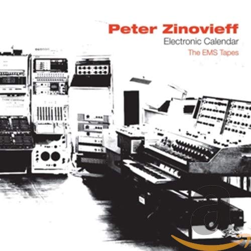

© Matrixsynth - All posts are presented here for informative, historical and educative purposes as applicable within fair use.
MATRIXSYNTH is supported by affiliate links that use cookies to track clickthroughs and sales. See the privacy policy for details.
MATRIXSYNTH - EVERYTHING SYNTH
© Matrixsynth - All posts are presented here for informative, historical and educative purposes as applicable within fair use.
MATRIXSYNTH is supported by affiliate links that use cookies to track clickthroughs and sales. See the privacy policy for details.
MATRIXSYNTH - EVERYTHING SYNTH