Showing posts sorted by relevance for query SOCKET ONE. Sort by date Show all posts
Showing posts sorted by relevance for query SOCKET ONE. Sort by date Show all posts
Thursday, July 31, 2014
KOMA Elektronik Introduces Attenuator Cable for Eurorack and More
Introducing: KOMA ATTENUATOR CABLE Published on Jul 31, 2014 KOMA Elektronik
"The Attenuator Cable is a cable with one jack input socket on one side, an output socket on the other side and a slider in the middle that gives the user the opportunity to attenuate both CV and audio signals traveling between modules. You simply connect a 3,5mm patch cable to the input socket of the Attenuator Cable and connect the output jack plug to any input of your liking. You can use the slider in the middle of the cable to attenuate and adjust the signal, easy peasy!
The cable design has been optimized to function with any CV or audio signal and with all known and widely available 3,5mm jack cables.
More information and sales:
http://koma-elektronik.com/?product=k...
KOMA Elektronik offers free worldwide shipping for all preorders of 5 cables or more made from our website! All pre-orders ship on August 21st 2014."
And the press release:
"After releasing the modular Kabelhänger at Musikmesse earlier this year, Berlin-based instrument manufacturer KOMA Elektronik has now released a new innovative solution for modular synthesists: the Attenuator Cable.
The Attenuator Cable is a cable with one jack input socket on one side, an output socket on the other side and a slider in the middle that gives the user the opportunity to attenuate both CV and audio signals traveling between modules. You simply connect a 3,5mm patch cable to the input socket of the Attenuator Cable and connect the output jack plug to any input of your liking. You can use the slider in the middle of the cable to attenuate and adjust the signal, easy peasy!
At KOMA we always understood the importance of attenuation, this is why we implemented control voltage attenuators in all of our modular designs; it's useful to keep everything running the way it is supposed to and to match voltages for different modular platforms. The Attenuator Cable gives you dedicated control for every signal coming from or going to modules without input attenuators, which there are a lot of! Since it is not a module, but a cable, you don't waste any space in your case and you can use as many cables as you like in one setup. The cable design has been optimized to function with any CV or audio signal and with all known and widely available 3,5mm jack cables.
The Attenuator Cable is available for preorders from KOMA Elektronik's website and from KOMA dealers worldwide. KOMA Elektronik offers free shipping for all pre-orders of 5 cables or more from our website!
MRSP is 9 € per cable (Incl. EU VAT) and 39 € for a pack of five cables."
Wednesday, February 23, 2011
DOEPFER A 154 SEQUENCER CONTROLLER
link to more items at the auction.
via Doepfer
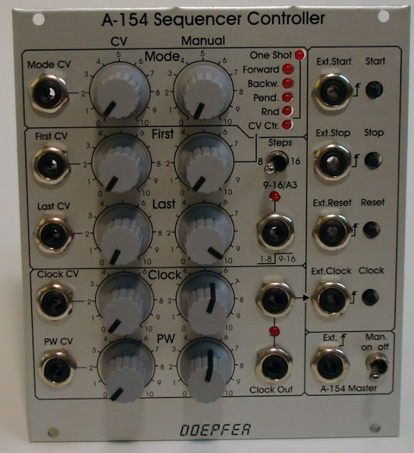
"Module A-154 is a supplement to the A-155 Analog/Trigger Sequencer module. It offers a lot of new features that are not available in the basic control unit of the A-155. The A-154 is used to replace the control unit of one or two A-155, i.e. the section marked "Control" with Start / Stop / Step / Reset buttons and inputs in the upper left corner of the A-155 front panel. If the A-154 is used to control the A-155 the control section of the A-155 is put out of action.
These are the features of the A-154:
Friday, January 10, 2014
Doepfer A-154 Enhanced Sequential Controller
Note: Auction links are affiliate links for which the site may be compensated.
via this auction
"module a-154 is a supplement to the a-155 analog/trigger sequencer module. it offers a lot of new features that are not available in the basic control unit of the a-155. the a-154 is used to replace the control unit of one or two a-155, i.e. the section marked "control" with start / stop / step / reset buttons and inputs in the upper left corner of the a-155 front panel. if the a-154 is used to control the a-155 the control section of the a-155 is put out of action.
these are the features of the a-154:
* several running modes: forward, backward, pendulum, random, cv controlled step adressing. all modes are available as loop or one-shot.
* led display of the 5 different current modes and one led for loop/one-shot display
* manual and voltage controlled selection (with attenuator) of the running mode. if no external control voltage is applied one of the 10 modes (5 modes x 2 loop/one-shot) is simply selected with a rotary knob. the cv input with attenuator is used to modulate the running mode with an external control voltage (digital high/low cv to switch between two modes or continuous analog cv to sweep through different modes). with the combination of manual control and cv with attenuator it is possible e.g. to use only two neighbouring modes (e.g. forward/backward) or sweep through all possible running modes
Wednesday, September 04, 2013
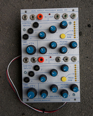
SPUTNIK DUAL DEFECT PROCESSOR MODEL 289
Published on Sep 4, 2013 romanfilippov·10 videos
This one in via Roman Filippov.
Playlist (use the controls on the bottom of the player to forward through videos - 4th video on shows module):
SPUTNIK DUAL DEFECT PROCESSOR MODEL 289 - SAW CORE OSCILLATOR
SPUTNIK DUAL DEFECT PROCESSOR MODEL 289 - SINE CORE OSCILLATOR
SPUTNIK DUAL DEFECT PROCESSOR MODEL 289 - DUAL FM OSCILLATOR SCOPE
SPUTNIK DUAL DEFECT PROCESSOR MODEL 289 - DUAL FM OSCILLATOR DEMO
SPUTNIK DUAL DEFECT PROCESSOR MODEL 289 - HARMONIZER / PITCH SHIFTER
SPUTNIK DUAL DEFECT PROCESSOR MODEL 289 - BITCRUSHER / SONIC DECIMATOR
SPUTNIK DUAL DEFECT PROCESSOR MODEL 289 - KARMINUS-WEAK SYNTHESIZER
SPUTNIK DUAL DEFECT PROCESSOR MODEL 289 - PLATE REVERBERATOR
SPUTNIK DUAL DEFECT PROCESSOR MODEL 289 - HALL REVERBERATOR
SPUTNIK DUAL DEFECT PROCESSOR MODEL 289 - TALKER
Some details via Roman on Muff's:
"we (Roman Filippov and Alex Pleninger) are glad to introduce the result of almost a year of development, coding, electronic tests and just complex work in general - Sputnik Defect Processor Model 289.
this device is crafted to precisely comply the modular standards of Buchla Electric Music Box better known as Buchla 200 and Buchla 200e.
the core of the 289 is a Digital Signal Processor which takes all the computations in sound transforming and generating. around it one may observe some controllable analogue parameters such as Balance and Regeneration, they are independent for each audio channel. both DSP cores have 8 independent Programs or Algorithms per core and each such algorithm has three voltage controllable parameters, varying from program to program. each core can be expanded via another 8 programs on external EEPROM chip. one of the most exciting feature is the variable Timebase which affects a lot of nuances in every algorithm's behavior.
apart from conventional stuff like reverbs, delays and various modulations the Model 289 offers quite unique solutions such as fm-synthesis, wide sonic range generators, human throat modelling, simple spectrum transfer facility, pitch-to-cv conversion, pitch shifting, audio looping, several sound destructors, pitch class generator, karplus-strong synthesis and many others, including some auxiliary programs. and the program list is ever-growing, new programs are always on the way.
we hope this module will take its place in every Buchla system whether it is a baby 4U boat or two 18U cabinets mighty electronic workbench.
ALGORITHMS
OSCILLATORS
we offer two oscillator programs, both of them work in audio range from 25 to approximately 3000 hz.
the controls are the following:
x - pitch.
y - wavemorphing.
z - wavefolding.
audio inputs 1 and 2 support amplitude and frequency modulations respectively.
on the output 1 you'll get final waveform morphed and folded, if any.
the second output provides the sub-oscillator one octave below the main one.
as for y and z controls, the first one continuously morphs the osc core (saw or triangle, depending on chosen program) from saw through triangle to half-inverted saw or from triangle through sine to square. in the case the wavemorphing is set to square, the wavefolding performs as pwm controller. in any other situations z-pot folds the wave in a manner of mathematical reflection at the given threshold. all these are pretty straight-forward, even if sounds a bit messy. you may observe the oscillators behavior in the attached [above] video footages.
Wednesday, November 12, 2008
DOEPFER A-188-2 TAPPED BBD DELAY
 via this auction
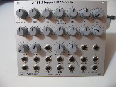
"A-188-2 is another module that is based on a so-called Bucket Brigade Device (BBD). If you are not familiar with BBDs please refer to the A-188-1. There you can find some details about this special type of circuits.
The main difference between A-188-1 and A-188-2 is the type of BBD circuit that leads to completely different module principles and sounds. The A-188-1 uses different single BBD chips with one signal input and one signal output only. In contrast the A-188-2 uses as so-called tapped BBD that has available six outputs - the so-called taps after the BBD stages 396, 662, 1194, 1726, 2790 and 3328. In the A-188-2 we use this special BBD circuit (MN3011) to obtain these module features:
The module has available two separate mixing sub-units. For both mixers the levels and polarities of each BBD output can be adjusted to obtain two different mixtures of the BBD outputs. A new type of potentiometers with center detent and center terminal is used for the BBD mixing controls to have a better feel for the neutral position. Each mixer has a wet/dry control at its output that allows choosing between the pure input signal (original), the BBD mix or anything in between. The two outputs can be treated as stereo outputs but it is also possible to use one of the outputs for other applications (details in the next paragraph).
 The A-188-2 has a feedback section available that is very similar to the one in the A-188-1. But as we now have 6 different BBD outputs available 6 different feedback types are possible. The feedback input socket is normalled to the "396" output (not to "1194" as shown in the scheme, the front panel is correct). But by patching the feedback socket to any of the single output sockets another BBD tap can be used for the feedback to obtain different sounds. Even external feedback processing is possible (e.g. with a VCA for voltage controlled feedback). The feedback control has polarizer function, i.e. the neutral position is at the center. Left from the center the feedback signal is subtracted from the input signal, right from the center it's added (negative/positive feedback). Even for this potentiometer the new version with center detent is used.
A special feedback can be obtained if one of the mix outputs is used for the feedback function. In this case for each tap the positive or negative feedback share can be adjusted. This leads to multiple peaks and/or notches in the frequency response of the module.
For each tap of the BBD a separate output socket is available. These sockets can be used for changing the feedback loop - as mentioned above -, for voltage controlled mixing of the taps - e.g. with the voltage controlled mixer A-135 or other applications that require access to each single tap.
The A-188-2 uses the same high speed VCO (HSVCO) for the BBD clock as the A-188-1. The clock and consequently the delay time can be controlled manually (delay control) and by the two control voltage inputs CV1 and CV2. The sensitivity of CV1 is approximately 1V/oct. CV2 is equipped with a polarizer (a new type of potentiometers with center detent). The HSVCO has a clock output available that is normalled to the clock input socket. These sockets can be used to link different BBD modules and to run them with the same clock. But even other applications with frequency dividers (e.g. A-163) or PLL (e.g. A-196) are conceivable. A voltage composed of the manual delay control, CV1 and CV2 is available at the CV out socket, e.g. to control an external clock suppression filter as the A-188-2 is not equipped with such a filter (same as for the A-188-1)." more info on the Doepfer website.
Tuesday, January 09, 2007
Oberkorn Sequencer
 No title link. Just the shot via this auction.
Details (I'm guessing this is the whole manual):
"Overview
Whilst most new analogue sequencers only offer a limiting 8 steps, the Oberkorn offers the all important 16 steps. It is a multi-channel true analogue sequencer with some remarkable features. Below are a list of main features:
1 Control Voltage channel.
2 separate Gate channels. The switches are 3 position providing the 2 Gate outputs, with centre being off.
Clear step LEDs. The 16 step LEDs are colour coded so locating whole note steps is easy.
Reset to 16. Just about all other analogue sequencer have an inherent error, in that after resetting the machine (to step 1), when restarting the sequencer, it actually starts on step 2! With our Reset to 16, this problem is overcome.
For more details on all features of Oberkorn , please read the whole manual - don’t miss any of it’s cool features!
About Analogue Sequencers
Saturday, September 04, 2021
Doepfer Product Announcements for SUPERBOOTH21
via Doepfer
"Superbooth 2021 is just around the corner. The Superbooth team around Andreas Schneider managed it with their hygiene and safety measures that the event can happen and personal contacts are possible again. The Superbooth takes place from 15 to 18.09.2021 in Berlin. More information is available at the Superbooth Website. We plan to present these new products and would be happy to welcome you at our booth (presumably B047 in the 'Bungalow-Dorf')."
Left: (A-100PB with a keyboard built into the lid, 37 keys, midi interface with 3.5 mm stereo jack socket)
This is the "small brother" of the monster base A-100PMB. It is very similar to the A-100PMB but has only half the width (2 x 84 HP for installation of modules). The suitcase versions A-100P6 or A-100P9 can be positioned on top of the A-100PB because the width of the A-100PB is a bit more than the width of A-100P6/P9 and the footprint of the A-100PB is adapted to the depth of A-100P6/P9. A-100PB is equipped with one power supply (1200mA) and two bus boards. The bus boards are located in the rear area (even those for the modules that are mounted in the front row). This was necessary to take advantage of the full height of the front area for installation of A-100 modules.
Sunday, March 14, 2021
Rare AVP Synth PolyRhythm
Note: Auction links are affiliate links for which the site may be compensated.
via this auction
You can find demos of one in previous posts here.
 "AVP PolyRhythm dual analog filter + phaser. These are extremely rare as only 20 were ever made. It has two VCFs: Polivoks filter and Ritm-2 filter. It uses authentic Soviet components and circuity in accordance with well-known Soviet synthesizers, produced in USSR back in the 80's and 90's. The Polyvoks has low-pass and band-pass with one input and two outputs (one for each filter) and the Ritm-2 has low-pass with one input and one output. It has an internal LFO and CV inputs for both sides.
One pot was replaced by a certified synthesizer repair store after I accidentally broke it trying to pull off a KickDisk. The replacement pot is the same value and taper as the original.
Power supply included! (For areas of the world with 120V mains)
Specs:
Method of signal processing: analog;
Voltage Controlled Filters (VCF): two types — POLY (Polivoks filter) and RHYTHM (Ritm-2 filter);
The low frequency oscillator (LFO): one — triangle;
Audio inputs: two — mono jack socket for 6.3mm;
Audio outputs: three — mono jack socket for 6.3mm;
CV inputs: two — mono jack socket for 6.3mm — 0V to +10V for Poly and -10V to +10V for Ritm-2;
Controls: 8 knobs, 5 switches;
Power requirement: 12V AC @ 400 mA;
Hard plastic black case;
Weight: 1kg;
Dimensions: L13,5 x W18,5 x H5,5 (cm);"
via this auction
You can find demos of one in previous posts here.
 "AVP PolyRhythm dual analog filter + phaser. These are extremely rare as only 20 were ever made. It has two VCFs: Polivoks filter and Ritm-2 filter. It uses authentic Soviet components and circuity in accordance with well-known Soviet synthesizers, produced in USSR back in the 80's and 90's. The Polyvoks has low-pass and band-pass with one input and two outputs (one for each filter) and the Ritm-2 has low-pass with one input and one output. It has an internal LFO and CV inputs for both sides.
One pot was replaced by a certified synthesizer repair store after I accidentally broke it trying to pull off a KickDisk. The replacement pot is the same value and taper as the original.
Power supply included! (For areas of the world with 120V mains)
Specs:
Method of signal processing: analog;
Voltage Controlled Filters (VCF): two types — POLY (Polivoks filter) and RHYTHM (Ritm-2 filter);
The low frequency oscillator (LFO): one — triangle;
Audio inputs: two — mono jack socket for 6.3mm;
Audio outputs: three — mono jack socket for 6.3mm;
CV inputs: two — mono jack socket for 6.3mm — 0V to +10V for Poly and -10V to +10V for Ritm-2;
Controls: 8 knobs, 5 switches;
Power requirement: 12V AC @ 400 mA;
Hard plastic black case;
Weight: 1kg;
Dimensions: L13,5 x W18,5 x H5,5 (cm);"
Sunday, December 21, 2014
New Doepfer A-160-5 VC Clock Multiplier/Ratcheting Controller & A-139-2 Headphone Amplifier
"Module A-160-5 is a voltage controlled clock multiplier. The incoming clock signal (socket Clock In) is multiplied by a factor that depends upon the control voltage on socket CV In (0...+5V) and the position of the Mode switch. The multiplied clock signal is available at the socket Clock Out. According to the position of the Mode switch different clock multiplying factors are assigned to the control voltage. With 0V CV no clock output is generated. With increasing CV integer factors (left position of the mode switch), power of two factors (middle position) or a mix of both (right position) are obtained. Nine LEDs are used to show the currently selected multiplying factor. In addition two LEDs are used to display the incoming and outgoing clock signal.
The module can be used for all kind of clock multiplying applications. One important example is the generation of so-called ratcheting sequences. The band Tangerine Dream is famous for this kind of sequences. A normal sequencer generates only one gate signal per step. A ratcheting sequence may have also more than one gate pulses per step. This function can be obtained by using the A-160-5: one CV output of the sequencer is used to define the number of gate pulses per step. If the control of the step in question is fully CCW the generated CV is 0V and no gate signal is generated (mute of the step). When the control of the step in question is turned clockwise one, two or more gate pulses are generated depending upon the position of the mode switch and the voltage generated by the CV at this step."
A-139-2
"two-channel headphone amplifier
two audio inputs with level controls
Input 1 is normalled to Input 2
common loudness/master level control
headphone output (stereo 1/4" jack socket)
max. output power ~ 2 W per channel (@ 8 Ohm load)
DC coupled inputs and outputs (i.e. also useful for other applications like small loudspeakers, lamps, LEDs, magnets, motors - provided that the power is sufficient)"
Monday, May 27, 2019
Doepfer A111-6 Sound Demo (no talking)
Published on May 27, 2019 Bonedo Synthesizers
A-111-6 Miniature Synthesizer
Module A-111-6 is a complete miniature monophonic synthesizer module that has these features available:
VCO
Tune: manual tune control (with an internal jumper the range can be set to ~ +/-1 half an octave or ~ +/-2.5 octaves)
Oct.: range switch -1 / 0 / +1 octave
Mod.: modulation depth (attenuator wired to the Mod. socket)
Dest.: switch that is used to address the modulation to frequency modulation (position FM) or pulsewidth modulation (positon PM), in center positon no modulation
PW: manual pulsewidth control for rectangle waveform, PW can be also modulated by the Mod. input as mentioned above
Wave: waveform switch (sawtooth / off / triangle), the sum of the waveform chosen by this switch and the rectangle is fed into the VCF (to turn the rectangle off the PW control has to be set fully CCW or fully CW)
1V/Oct. (socket): external CV input for VCO frequency (1V/octave)
access to internal bus CV (via jumper, optional, please remove the bus jumper if this feature is not used to avoid unwanted frequency modulation as then the unused CV line of the bus works as a kind of antenna)
triangle core VCO, frequency range about 32Hz ... 8kHz (??? still to be specified)
Balance unit
The balance unit is made of two VCAs which are controlled by the sum of manual Balance control and the balance CV input in the opposite direction.
The audio input of VCA1 is hard-wired to the VCO output, audio input 2 is connected to the socket Ext.In.
The output of the balance unit is used as audio input for the VCF
Bal.: manual balance control, fully CCW the internal VCO is used, fully CW the external signal (Ext.In) is used, at center position both signals have about the same level
CV Bal.: CV input for balance (range about 0...+5V)
Ext. In: external audio input for VCA2, about 5 Vpp level required for similar loudness as the internal VCO
this socket is normalled to the internal VCO suboctave f/2 signal (rectangle with half the frequency), if no external signal is applied the suboctave signal is used as the second signal for the balance unit
Wednesday, May 25, 2011
Richard Lainhart - Bellingham Electronic Arts Festival Lecture & Performance
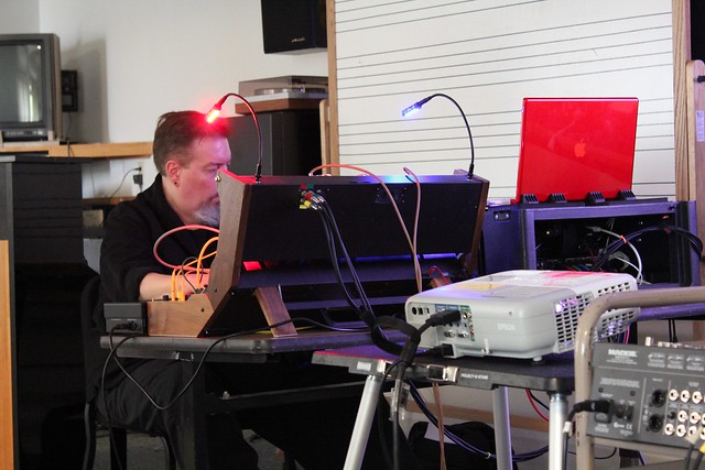
Slideshow of Richard Lainhart's lecture at the Bellingham Electronic Arts Festival (BEAF), Friday, May 6, 2:PM PST, 2011 (mentioned in this post). Below is a video of the Buchla and Haken Continuum portion of the lecture followed by a performance of Olivier Messiaen's Oraison written for the ondes Martenot at the 48:00 mark (see this post for the original version and this post for another performance by Richard). You will notice Richard makes references to earlier parts of the lecture. These included his training on the CEMS modular synthesizer system and the ondes Martenot (don't miss this post and this post on the CEMS). See the labels at the bottom of this post for more info on each. I will upload those videos at a later date. They were background to Richard's experience with early modular synthesizers and controllers that eventually lead him to the Buchla and Haken Continuum. It was a great lecture and I hope you enjoy it. Be sure to bookmark this one. I also want to thank Richard Lainhart for doing lectures like these. They are a rare treat.
YouTube Uploaded by matrixsynth on May 19, 2011
The following is a full transcript. BTW, if anyone is interested in transcription services, let me know.
"RICHARD LAINHART: BUCHLA AND HAKEN CONTINUUM LECTURE
Speaker: Richard Lainhart
Lecture Date: May 6, 2011
Lecture Time: 2:00 p.m. PST
Location: Western Washington University
Event: Bellingham Electronic Arts Festival 2011 (BEAF)
Length: Digital AVI recording; 57 minutes 32 seconds
[Beginning of recorded material]
Richard Lainhart: Okay. What I want to do now is actually talk a little bit about the system itself here and about the design of the system and explain what's actually happening here and why it's designed this way, and again, my focus on, on expression. So this is, as I mentioned, this is the Buchla 200E. This is a current electronic music instrument that is still being made now by Buchla. Don Buchla again was a contemporary, or is a contemporary of Bob Moog, and he took a very different path than Moog did. And one of the reasons I think that Moog's instruments became so popular, of course the Mini Moog was like the first real break-out electronic music synthesizer, was that Moog's instruments had keyboards on them. They had black and white keyboards. And you could use them to play, you could use them to play rock and roll with them basically because you could plug them into a really loud amplifier and it could be louder than a guitar. And it could be a bass, you know, it could be louder than a bass and all that sort of stuff. And of course a lot of, you know, a lot of wonderful music was made with that instrument.
LABELS/MORE:
beaf,
Buchla,
CEMS,
events,
Featured,
Haken,
MOOG,
Ondes Martenot,
synth tutorials,
theremin,
Video Processing
Saturday, July 20, 2013
Pink Noise Technology presents: OrangeMeetsPink eeprom for Double Andore
"The OrangeMeetsPink eeprom you are (hopefully) holding in your hand containins waveforms for the Harvestman Double Andore eurorack module. To be able to use those, you first have to install it into your Double Andore (doh!).
[image via Richard Devine on Facebook]
Don't worry, that's easy.
Start by locating the similar looking chip sitting in a socket on the back side of your Double Andore (there is only one). Note that the chip has a small cutout in one of the short sides, indicating direction (this cutout or similar indication of direction is in the socket holding the chip as well).
Now, CAREFYLLY remove the chip from the socket (inserting a small flathead screwdriver between the chip and the socket holding the chip, and carefully wiggling and turning the screwdriver usually does the trick. Be careful not to bend the legs of the chip, in case you want to switch back to using the original). Then, place the new eeprom in the socket, making sure it's positioned in the same direction as the old one (cutout matching socket cutout), and gently press it into place.
Reconnect your Double Andore, and you're done!
Waveforms
The OrangeMeetsPink eeprom contains two sets of 16 waveforms each. The first bank of 16
are the same as the ones on the original Double Andore eeprom (the Orange bank). By holding the CV select button until a small dot appear in the display for the choosen side you switch the Double Andore to using the second bank (the Pink bank) containing the following waveforms:
Tuesday, March 25, 2014
Doepfer A-107 Multitype Morphing Filter
Note: Auction links are affiliate links for which the site may be compensated.
via this auction
"Module A-107 is a completely new voltage controlled filter that has available 36 filter types: different versions of low pass, high pass, band pass, notch, all pass and filters with new response curves that have no name up to now. The frequency response curves of the 36 filters available in the A-107 are shown in the graphics at the end of this page. The filters are organized in two groups of 18 filters each. The transition between different filter types within one group can be soft (morphing) or hard (switching).
The filter was inspired by the ERWIK Musikelektronik Multimode Filter, which is based on the filter used in the Oberheim Matrix 12 resp. Xpander (thanks to Jesper Erwik Johansson for his assistance and permission to use his idea in our A-107 module). The possibilities of the A-107 go far beyond these filter designs as a lot of new filter types are available and the transition between filters can be soft (morphing) or hard (switching) and the filters can be arranged in 64 different voltage controlled filter chains.
The transistion between the different filter types is controlled by two parameters:
Filter Step (marked Step at the front panel)
Morphing Time (marked Morph at the front panel)
For both parameters manual control, one CV input with attenuator and one CV input without attenuator are available.
The 36 filter types can be arranged in filter chains (resp. filter sequencer or filter orders) so that this sequence of filters is passed through while the control voltage changes from 0...+5V. Each chain consists of 32 steps. 64 filter chains can be programmed by the user and stored in the non-volatile memory of the module. The following controls are used to program the filter chains:
Step: button to address the desired step (1...32) within the filter chain in combination with the value encoder
Filter: button to select the filter number (1...36) that is assigned to the current step within the chain in combination with the value encoder
Chain: button to select one of the filter chains (1...64) in combination with the value encoder
Program: button to store the current filter chain in one of the non-volatile memories (1...64) in combination with the value encoder
Value: endless rotary encoder to change the parameter selected with the buttons
3 digit Display (the first digit indicates of the current value shows Step "S", Filter "F" or Chain "C", the second and third digit display the number)
Additionally a "clocked" mode is available. This means that the steps of the currently selected filter chain are selected one after another. Each positive transition of the Clock signal calls up the next filter of the chain (jack socket marked Step Clock). A positive trigger at the Step Reset input (jack socket marked Step Reset) resets to the first filter of the current filter chain. This allows e.g. to switch between the filters of the currently selected filter chain in sync with a sequencer.
Of course the standard VCF controls are available: manual filter frequency control, one CV input with attenuator and one CV input without attenuator.
In addition voltage controlled resonance with manual control, CV input with attenuator and CV control without attenuator are available. For the filters of the first group (1...18) self-oscillation is possible, the filters of the second group (19...36) do not feature self-oscillation.
On top of it a final VCA is available (even with manual control, CV input with attenuator and CV input without attenuator).
The filter design is 100% analog (CEM filter chip). Only the morphing control and memory managing is carried out by a microcontroller.
Remark: Because of technical reasons the transition between the two filter groups (1...18, resp. 19...36) cannot be carried out soft as capacitors have to be switched. Soft transition (i.e. morphing) is possible only within the filter group (i..e. within the filters 1...18 or 19...36). Switching between filters causes a "click" if the filters are from different groups.
For more detailed information please look at the English user's manual A107_man.pdf"
Saturday, August 31, 2013
Doepfer A-107 Multitype Morphing Filter Eurorack Module
Note: Auction links are affiliate links for which the site may be compensated.
via this auction - learn how to sell on eBay here
"module a-107 is a completely new voltage controlled filter that has available 36 filter types: different versions of low pass, high pass, band pass, notch, all pass and filters with new response curves that have no name up to now. the frequency response curves of the 36 filters available in the a-107 are shown in the graphics at the end of this page. the filters are organized in two groups of 18 filters each. the transition between different filter types within one group can be soft (morphing) or hard (switching).
the filter was inspired by the erwik musikelektronik multimode filter, which is based on the filter used in the oberheim matrix 12 resp. xpander (thanks to jesper erwik johansson for his assistance and permission to use his idea in our a-107 module). the possibilities of the a-107 go far beyond these filter designs as a lot of new filter types are available and the transition between filters can be soft (morphing) or hard (switching) and the filters can be arranged in 64 different voltage controlled filter chains.
the transistion between the different filter types is controlled by two parameters:
* filter step (marked step at the front panel)
* morphing time (marked morph at the front panel)
Thursday, May 20, 2010
OBERHEIM MATRIX-6 - “AUDIOPHILE VERSION”
Note: Auction links are affiliate links for which the site may be compensated.
via this auction
"Ever wonder what would happen if one applied the same upgrade principles we commonly use in high-end audio applications and apply it to ONE of our favorite vintage synths?
The result is what I am listing here as the Matrix 6 –“Audiophile Version” and the sonic results are amazing!!
I repair vintage synths on the side and acquired this Matrix 6 last year in non-working condition. We all know how awesome the classic Oberheim synth circuits are, there’s no questioning that! But many of us engineers know that a circuit is only as good as the quality of parts it is comprised of. Furthermore, many synth manufacturers cannot afford to use the very finest components in manufacturing due to cost constraints in efforts to try and keep the sales MSRP’s down as low as possible. But we don’t have to be limited to that thinking any longer in the 2nd hand market! Therefore, I decided to apply the “audiophile concept” to this Matrix 6 and see what we’d end up with. Below is an outline of the improvements:
* Power Supply Rebuild – pcb cleaned and all critical solder joints re-soldered with special audiophile-grade lead-free solder. Yes, the solder does make a difference folks in the timbre of the circuit! Next, High-end Nichicon Muse Gold series capacitors were used throughout the power supply. (See photo). This greatly enhances the resolution and clarity of the synth and also enhances the “smoothness” and reserve power of the Bass response of the synth since the power supply is responsible for powering all the circuits in the entire synth. Amazing smooth, Fat, rich, Bass now! Power supplies are a very critical component in any synth, just as they are in a tube preamp or any other electronic audio device. This really is no amazing breakthrough knowledge, just smart application of known wisdom.
* The main processor board had a dead battery. This was partly the cause of the original malfunctioning synth. Not only was a fresh battery installed, but a high-quality battery socket was soldered to the pcb so that future battery replacement is very easy if necessary.
* All chips on the processor board were removed and cleaned. Special, non oil-based socket enhancement fluid was used when replacing the IC’s.
* The Processor pcb was then re-loaded with a fresh data dump from the 1100 patch disc included.
* Audio processor pcb was removed and cleaned. All CEM VCO chips were removed and cleaned and replaced with socket enhancement fluid.
* The output pcb on these Matrix synths are very important to the overall sound quality output. The slider potentiometer was rebuilt with Alpha pot parts and re-assembled. Very nice, smooth, action and feel now. Much better than original. The output IC amp is tied to two 10uf caps, which were upgraded to Nichicon Muse Gold caps since this effects the timbre (tone) of the overall output. Small parts, Yes … but very important in the circuit! Again all Solder joints were improved on this pcb as well.
* Keyboard was removed from chassis and disassembled. Rubber boot pcb contact covers were removed and cleaned. This is where we commonly find dried Coke spilled on the keyboard from “who knows what gigs”. This has a tendancy to mess with the contact integrity of the keyboard action, causing misfires of keys etc. The fix is to clean and carefully re-assemble. Keys tops were then polished with plastic polish.
* Entire chassis was cleaned and repainted where possible. The Chassis end pieces were painted with high-quality metallic paint to put a spin on the fact that this synth is “Special Audiophile Edition” now.
* Modulation pots were cleaned and lubed and solder joints re-worked since the headphone output circuit is integrated into this assembly. Headphone output now has increased resolution and clarity.
That about sums it up in the upgrade department for this synth. There are more improvements one could make such as gold-plated female chassis IEC socket and Cryogenically-treated 12 guage power cord etc, but I’ll save that for a future listing or another upgrade project. Warning folks, while all these improvements are awesome and rewarding, they are very time-consuming, as any competent synth tech will tell you. I have about 25 to 30 hours in this one! Will this start a trend? Perhaps...depending upon demand, but your ears will "Hear the Difference"!" Note the side panels on this Matrix-6 are non-standard gray. inside a Matrix-6
Tuesday, July 24, 2007
Hataken Interview

Back on March 31, I put up a post on Hataken, a Japanese DJ artist who primarily uses analog synths. At the time, Shane Chisolm, the manager of Don Juan Dracula mentioned Hataken was working on a remix version of DJD's "Take Me Home". Shane asked me if I'd be interested in doing an interview with Hataken, and I thought why not. It would be interesting to hear his perspective on the world of synths as a live DJ artist. The following is the result of that interview. Note, this is a long one. You will want to use page down to scroll through. If it is too long for you, I recommend reading one or two questions each time you visit the site. Each DIY item below would typically have been a separate post. There is a lot of interesting stuff here. That said, I start with an introduction followed by asking Hataken how it all started for him. Note the focus is primarily on synths as this site is about everything synth, and Hataken delivers. The gear he has both worked with and designed to meet his specific needs is overwhelming. There's also an interesting interlude on experimenting with frequency counters to produce specific frequencies of sound known to have healing properties, and of course there is a bit of the age old discussion of digital and analog.
Before we start the interview, I want to thank Hataken for taking the time out for this, and I want to thank Shane for suggesting it. It's a fascinating history of a DJ synth artist with interesting perspectives that I'm sure I will come back to over time. Be sure to check out the video and link to more at the end. And of course be sure to check out Hataken's website.
1. Can you tell us a little bit about yourself?
LABELS/MORE:
Alternate Controllers,
Delta Music Research,
DIY,
Eventide,
Future Retro,
Highly Liquid,
Metalbox,
MOTK,
SynTom,
Ultimate Sound,
Wavemakers
Tuesday, August 27, 2019
Roland HS-60 / Juno-106 SN 540181
Note: Auction links are affiliate links for which the site may be compensated.
via this auction
 "The Roland HS-60 is IDENTICAL to the Juno 106 but it has onboard speakers, HOW COOL! Same circuit boards, voice chips, everything. You've heard it and you know how good they sounds and now you need it in your arsenal. Super lush, deep strings, sweeps, filters, effects, organs, AND it is fully equipped with midi so you can run it with your modern digital setup. This one is made in May of 1985.
Its in nice shape with next to no wear. The 80's graphics look fantastic. There is a little wear here an there but nothing much. You can see from the pictures how clean it is. There are no scratchy pots for they have been cleaned. All of the black coating was removed from all voice chips and sound fantastic. New blue LED's, because they look awesome. The numeric display, the "A" preset LED and one of the chorus' were kept red. I think it looks cooler with a mix of both colors. The original battery has been replaced with a new one and a socket so if the battery ever goes out, just pull the battery and pop a new one in. The 2-prong power socket has been updated to a universal 3-prong socket. This one is road ready and needing to see some stage and studio action."
via this auction
 "The Roland HS-60 is IDENTICAL to the Juno 106 but it has onboard speakers, HOW COOL! Same circuit boards, voice chips, everything. You've heard it and you know how good they sounds and now you need it in your arsenal. Super lush, deep strings, sweeps, filters, effects, organs, AND it is fully equipped with midi so you can run it with your modern digital setup. This one is made in May of 1985.
 Its in nice shape with next to no wear. The 80's graphics look fantastic. There is a little wear here an there but nothing much. You can see from the pictures how clean it is. There are no scratchy pots for they have been cleaned. All of the black coating was removed from all voice chips and sound fantastic. New blue LED's, because they look awesome. The numeric display, the "A" preset LED and one of the chorus' were kept red. I think it looks cooler with a mix of both colors. The original battery has been replaced with a new one and a socket so if the battery ever goes out, just pull the battery and pop a new one in. The 2-prong power socket has been updated to a universal 3-prong socket. This one is road ready and needing to see some stage and studio action."
Tuesday, August 12, 2008
Circuit bent mechanical Furby sequencer linked to Korg SQ-10
YouTube via thenervoussquirrel.
Up for auction here.
"One of a new batch of four Furby Gurdies. This model allows you to program your own rhythms by rearranging screws inserted into the four wheels.
There is also a 'trigger out' socket, which has been used in the last section of the video to operate an old sequencer and synthesiser.
More details here"
via nervoussquirrel on the forum.
"Sometime prior to the 11th century A.D. a strange hand-cranked instrument called the hurdy gurdy appeared on the scene in Western Europe, drifting in and out of fashion but remaining in production to this day. In 1998 Tiger Electronics produced a scary children's toy called the Furby, and sold over 40 million of them in three years.
This auction is for the strange and terrible result of combining both of these phenomena - this is a rare chance to own your own Furby Gurdy!
This instrument involves four modified Furby toys that can be made to produce sound in a sequence by winding a handle. Each Furby has been 'circuit bent', which is a process that involves adding connections to the original electronic circuit board to create interesting new sounds.
When the handwheel is turned, four wheels operate four switches in a sequence. The sequence pattern is created by adding or removing screws from the 12 holes around the circumference of the wheels. Each of the four switches operated by turning the handwheel correspond to a Furby, causing it to make a sound as the screwheads pass.
Each Furby has six controls on the panel underneath it:
(1) Mute - turns off an individual Furby's sound
(2) Loop hold - captures a short loop of audio while a Furby is speaking
(3) Loop momentarily - useful for searching for a good sound before using 'Loop hold' to keep the sound
(4) Microswitch mode select - Switches between audio being produced by either the screwheads on the wheels or the gaps between the screwheads
(5) Crash - creates a stream of glitches and garbled Furby speech, random bleeps, crunches and hisses
(6) Reset - used to restore good health after the crash function
There is a main audio output socket on the front (1/4 inch jack), as well as four individual outputs on the rear of the unit.
There is also a socket on the rear of the unit that allows the switch under the fourth wheel to be used by an external device. Plugging a jack lead into this socket disconnects the fourth Furby and allows other devices to be triggered in time to the winding of the handwheel. In the video I have connected this socket to the step input of a Korg SQ-10 sequencer, so that the sequencer advances by one note every time a screwhead passes the switch.
There were four of these Furby Gurdies made - this auction is for one of the last two, serial number 00075.
High-quality switches and components have been used throughout, and build quality/soldering etc. is all very good. The casing is made of folded aluminium sheet and painted MDF, and the handwheel is solid machined aluminium. The rotating shaft has been mounted on bearings to ensure many years of lasting Gurdy goodness."
Sunday, March 20, 2011
Roland TR-707 Circuit Bent Drum Machine
"professionally circuit bent by the guys at CircuitBenders.co.uk...
Listen to some MP3 examples of the sounds this beast can make!
http://www.circuitbenders.co.uk/drummachine/TR707.html
Here is a list of the additions:
18 Way 3.5mm Jack Patchbay
Connections made between sockets on the patchbay cause distortion, ring modulation, sound swapping, modulation and otherworldy alien effects to be applied to the sounds. Each 3.5mm patchbay socket is home to a certain audio process or effect which either combines with the effect from another socket when they are patched together, or sometimes just produces an entirely new effect you've never heard before. Multiple simultaneous connections may also combine in unexpected ways to produce a brand new unexpected effect, giving you a virtually unlimited number of warped alterations and audio mutations. The only limit on the number of connections you can make at any one time are how many sockets and patch cables you have available. Connections can be made at any time or even switched in and out using the patchable switches.
2 x 3 Way patchbay multipliers
These are the 2 sets of 3 sockets to the left of the cartridge port. They further multiply the creative possibilities of the machine by allowing you to connect more than one plug to the same patchbay source.
2 x 3 Way Distortion Switches
These switches on the top right of the machine offer four types of distortion from mild over-driven crunch up to all out electro grinding. Each switch also has an off setting in the centre. You may want to go easy on the top switch as the distortion available is absolutely brutal.
2 x Patchable Switches
Four plugs and two switches on the top left enable you to route a plug from the patchbay to one of these sockets and then from the adjacent socket back into the patchbay. This effectively allows you to find two patchbay settings you like and then turn them on and off at the flick of a switch without having to keep re-patching.
HiHat Decay Knobs
The knobs in the bottom right corner control the decay of the Open and Close Hats, giving you much more control over the hats in your performance.
Audio Input Socket
Last, but by no means least is the audio input jack socket on the right hand edge of the machine. When a plug is inserted, the Hi-Hat sound is removed from the mix and replaced with the audio input controlled by the Decay Knobds detailed above."
Wednesday, October 19, 2005
CES ED-LAB
Update: Excellent point via the comments. Thanks Dave.
"Aren't these for more of what they can do, then for what they sound like. Basiclly, it gives a number of logic modulues to your banaplug modular.
After playing with my Nord Modular for a while, you get to really understand the power and flexibility of logic modules.
So the power is in what it does or doesn't do to your sound, rather then in it's sound creation abilty.
Though never played with one, so there could be some good sound making abilties.. i do see the diodes and tube...
Dave "
----------------
Currently on the *bay. Title link takes you to shots saved for posterity. This looks like one of those educational kits. Read below for details. I always wonder what one of these would sound like. My guess is nothing too impressive otherwise they'd be more popular, but who knows... If you do, please feel free to comment.
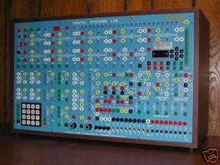
Notes from the auction also saved for posterity:
ANALOG MODEL 652.A ELECTRONICS SYSTEM LAB
6 DC power supplies regulated with fixed and variable outputs with both positive and negative fully protected supplies; 2 phase AC power source; waveform generator with sync, fvco, variable sine, square and triangle outputs from 1 Hz to 100Khz; meter for AC or DC voltage and DC current shunts; high impedance AC input to prevent over-loading; switches, resistors, capacitors, inductors, diodes, zener diodes, varactor diodes, transistors, lamps, op amps, radio coil, transformer, digital and linear IC socket, vacuum tube socket, PC, printed circuit, or breadboard slot; FET's, MOSFET's, UJT, SCR, Triac, Diac, and built-in speaker.
DIGITAL MODEL 703.A DIGITAL SYSTEMS LAB
A/D converter, D/A converter, follower/hold, scmitt trigger, comparator op-amp, one-shot, variable speed digital clock, counter and register, IC socket, PC, printed circuit, or breadboard slot; multiplexer, demultiplexer, encoder/decoder, 8 electronic switches, 10 flip-flops, 4 AND gates, 3 NAND gates, 3 OR gates, 4 Exclusive/OR gates, 3 NOR gates, 6 Inverter/NOT gates, keypad, and built-in speaker.
CONSTRUCTION AND CONDITION
The Ed-Labs are well constructed 1/8" aluminum panels each housed in 23.5" W x 14.5" H x 10" D formica cabinets. These were purchased from a Vocational School surplus sale and were described as operational to the auctioneer. There were no banana cables or manuals included. Both power-up but are untested by me (no cables). These instruments are very clean cosmetically. Each has a foil serial number sticker on the front panel and the 702 has its serial lightly scratched in small numbers under the keypad. There is a ding to the lower left corner of the 651 (see picture). The 651 is also missing a knob on a button switch at the bottom labeled "M" and a knob in the radio circuit. This knob mounts on a shaft that is sitting flush to its front panel casing. The 651 was missing one of its rubber feet, so I replaced those with a similiar white set of four. The original set of three will be included with the auction. Both units appear to be otherwise complete.
APPLICATIONS
The Ed-Labs can be employed as expanders for a modular synthesizer system; for circuit design, modification, experimentation; or as effective tools for those pursuing a general electronics education.
"Aren't these for more of what they can do, then for what they sound like. Basiclly, it gives a number of logic modulues to your banaplug modular.
After playing with my Nord Modular for a while, you get to really understand the power and flexibility of logic modules.
So the power is in what it does or doesn't do to your sound, rather then in it's sound creation abilty.
Though never played with one, so there could be some good sound making abilties.. i do see the diodes and tube...
Dave "
----------------
Currently on the *bay. Title link takes you to shots saved for posterity. This looks like one of those educational kits. Read below for details. I always wonder what one of these would sound like. My guess is nothing too impressive otherwise they'd be more popular, but who knows... If you do, please feel free to comment.

Notes from the auction also saved for posterity:
ANALOG MODEL 652.A ELECTRONICS SYSTEM LAB
6 DC power supplies regulated with fixed and variable outputs with both positive and negative fully protected supplies; 2 phase AC power source; waveform generator with sync, fvco, variable sine, square and triangle outputs from 1 Hz to 100Khz; meter for AC or DC voltage and DC current shunts; high impedance AC input to prevent over-loading; switches, resistors, capacitors, inductors, diodes, zener diodes, varactor diodes, transistors, lamps, op amps, radio coil, transformer, digital and linear IC socket, vacuum tube socket, PC, printed circuit, or breadboard slot; FET's, MOSFET's, UJT, SCR, Triac, Diac, and built-in speaker.
DIGITAL MODEL 703.A DIGITAL SYSTEMS LAB
A/D converter, D/A converter, follower/hold, scmitt trigger, comparator op-amp, one-shot, variable speed digital clock, counter and register, IC socket, PC, printed circuit, or breadboard slot; multiplexer, demultiplexer, encoder/decoder, 8 electronic switches, 10 flip-flops, 4 AND gates, 3 NAND gates, 3 OR gates, 4 Exclusive/OR gates, 3 NOR gates, 6 Inverter/NOT gates, keypad, and built-in speaker.
CONSTRUCTION AND CONDITION
The Ed-Labs are well constructed 1/8" aluminum panels each housed in 23.5" W x 14.5" H x 10" D formica cabinets. These were purchased from a Vocational School surplus sale and were described as operational to the auctioneer. There were no banana cables or manuals included. Both power-up but are untested by me (no cables). These instruments are very clean cosmetically. Each has a foil serial number sticker on the front panel and the 702 has its serial lightly scratched in small numbers under the keypad. There is a ding to the lower left corner of the 651 (see picture). The 651 is also missing a knob on a button switch at the bottom labeled "M" and a knob in the radio circuit. This knob mounts on a shaft that is sitting flush to its front panel casing. The 651 was missing one of its rubber feet, so I replaced those with a similiar white set of four. The original set of three will be included with the auction. Both units appear to be otherwise complete.
APPLICATIONS
The Ed-Labs can be employed as expanders for a modular synthesizer system; for circuit design, modification, experimentation; or as effective tools for those pursuing a general electronics education.
NEXT PAGE
HOME





© Matrixsynth - All posts are presented here for informative, historical and educative purposes as applicable within fair use.
MATRIXSYNTH is supported by affiliate links that use cookies to track clickthroughs and sales. See the privacy policy for details.
MATRIXSYNTH - EVERYTHING SYNTH


© Matrixsynth - All posts are presented here for informative, historical and educative purposes as applicable within fair use.
MATRIXSYNTH is supported by affiliate links that use cookies to track clickthroughs and sales. See the privacy policy for details.
MATRIXSYNTH - EVERYTHING SYNTH

