MATRIXSYNTH: Search results for The Usual


Showing posts sorted by relevance for query The Usual. Sort by date Show all posts

Monday, May 08, 2023

New Kaona Eurorack Modules Coming to SUPERBOOTH


video upload by Kaona modular music

Handcrafting of Skippy by Kaona


Mumack first test


"First sound of Mumack"

Switchy for Eurorack

video upload by

"Three switches to control the power supply of three Eurorack modules or three flying bus."

Transpos Eurorack

"Transpos is both a transposer and a three channel voltage adder or subtractor for Eurorack modular music"


Skippy is a matrix and non-matrix polyrhythmic sequencer (linear and logarithmic) which offers four completely independent tracks with a very simple interface: one button per track, one function per screen, no sub-menus.

Monday, April 02, 2018

Mr Woofer - Synth Demos


Published on Oct 6, 2017 Mr Woofer

Playlist:

1. Mr Woofer - Enter Space (Atari STE Demo)
"Enter Space!" says Sinclair Spectrum ZX through its Currah uSpeech synthesizer. The Atari STE and its Yamaha YM2149F chip in all its square wave glory does exactly that. The tools used to control the STE are NSQ (Near Synthesizer Quality), Chip Synth and MaxYMiser.

The powerful beats are coming from NI Massive except for the Hi-hats and noise bursts which are also Atari STE. As usual external reverb and delay are added. Hope you enjoy it!

Music and Sound Design by Mr Woofer (Konstantinos Kampanis).
Original footage and video editing by Mr Woofer.

Enjoy!

Thursday, March 04, 2021

SUPERBOOTH21 Safety First Edition Moved to September 2021


via SUPERBOOTH

"New date for SUPERBOOTH21

The decision has been made. The new date for the Safety First Edition of SUPERBOOTH21 is set for this summer, from September 15 to 18, 2021.

HerrSchneider: 'Even the greatest optimists must slowly acknowledge that the world will not be ready for larger, international gatherings in nine weeks now. That's why we've decided to move SUPERBOOTH21 to September.'

But if in the summer, then with really much outside! The organizers of the trade fair do not want to miss out on the opportunities offered by moving the event to the warm season. Thus, additional places in the outdoor area of the FEZ Berlin were included in the planning of the event.

At the new locations, Fuchsbau, Hüttendorf and the small forest behind the seaside stage, there will be outdoor exhibitors for the first time. All stations are connected by short walks and each offer a varied program of concerts and presentations on smaller stages, so that you don't have to miss the usual SUPERBOOTH festival feeling.

The open-air concept is intended to harmonize the usual relaxed atmosphere with the necessary safety measures in terms of distance and fresh air. For this purpose, half of the event space will be relocated to the spacious outdoor area. The exhibition areas inside the building will be reduced and thinned out in order to maintain the spatial distance between the participants and to avoid clusters of guests. Like the exhibition space, the guests will also be divided: For four hours each, in two groups of 500 people. This results in a moderate flow of visitors, who can experience the usual diverse selection of exhibitors in the reduced indoor area and then spend the rest of the day in the outdoor area, alternating with the second group.

In total, there are already several dozen confirmations from exhibitors who want to make their way to Berlin in September. Due to expected travel restrictions and existing planning obstacles, larger manufacturing teams directly postponed their participation to 2022. Likewise, it will not be possible for many overseas exhibitors to come to Berlin as early as the end of the summer. These will be offered alternative options for digital participation in the "Safety First Edition".

Ticket pre-sales will not start before May, as the current development of the health situation will of course continue to be monitored. The actual realization of the event is directly linked to the start of ticket sales in order to avoid costly refund processes.

SOOPERgrail
The first edition of the new fair for the celebration of the art of guitar building will take place next year. Then numerous exhibitors will present instruments from the acoustic and electric range, for testing, experiencing and discussing.
The focus will be on the practical use of the presented instruments, the communicative get-together and the inspiring exchange between users and passionate manufacturers.

sooperRADIO
The first radio show of the Superbooth team from Feb. 11 is archived for listening on the new homepage sooperRADIO.com. Studio guest Thomas Kircher - from SchneidersLaden - explains how to work with a modular synthesizer and Sacha Ketterlin answers questions about his production techniques. Andreas Schneider talks about his motivation to host SUPEBROOBTH21 and SOOPERgrail.

The next sooperRADIO is dated 08. April 2021."

https://www.superbooth.com

Wednesday, March 23, 2011

M-Audio Venom Review and Interview with Product Manager Taiho Yamada


A quick note: This review is long. You can jump to sections that interest you vs. reading it straight through if you prefer. This review focuses primarily on the synth engine for one single patch on the Venom. The Venom supports Multi mode with up to four multitimbral parts. Not only can you layer sound programs but you can set global parameters for the set. Be sure to see the Multi mode section of "Tips and Tricks via Taiho Yamada" at the end of this post. Taiho is the Lead Project Manager of the Venom and served as my contact during the review. I want to thank Taiho for his help and enthusiastic generosity. He is a true synthesist and the Venom is his baby.

Synth connections: Taiho previously worked at Alesis on the Andromeda A6. The DSP developer of the Venom worked on Radikal Technologies' Spectralis and the Accelerator. People that contributed to the presets via sound design include Richard Devine, Francis Preve, Mark Ovenden (Avid's AIR Instruments, ProTools VIs), Joerg Huettner (Waldorf, Access, Alesis), and of course Taiho Yamada.

*Don't miss the "Q&A with Taiho" section towards the end of the review. Also keep an eye out for "Taiho's Tips and Tricks" throughout the review in grey. You can find the consolidated list below the Q&A section.

Tuesday, September 07, 2010

DK SYNERGY II+ SYNTHESIZER, KAYPRO II & SYNHCS SOFTWARE


synergyII timbres Uploaded on Sep 5, 2010 xenmaster0


s 2 demo 1 441 final 320x240stream Uploaded on Sep 5, 2010 xenmaster0

Warning: this is a long post and can't be paged with the "click for more" link otherwise the videos will not load. Also, no time to parse the entire listing, so everything captured below for the archives.

via this auction

"DIGITAL KEYBOARDS SYNERGY II+

WITH KAYPRO II & SYNHCS 3.182 PROGRAMMING SOFTWARE, 14 FLOPPY DISCS OF SYNERGY TIMBRES, and 3 SYNERGY ROM CARTRIDGES

This is the legendary Synergy synthesizer. It comes with the Kaypro II CP/M computer I bought with the Synergy and the SYNHCS software used to program the Synergy. Three Synergy ROM cartridges are included, WC-1 and WC-2, the Wendy Carlos Voice cartridges 1 and 2, and the VCART 4 cartrdige, along with a null modem cable that you use to connect the Synergy synthesizer with the Kaypro II computer.

Using the Kaypro II computer running the Synergy Host Control System software (SYNHCS), you gain access to the full capabilities of the Synergy synthesizer. With the Kaypro II computer + SYNHCS software, you can program the Synergy synthesizer to generate any kind of sound you can imagine. Then you can save the timbres you create on floppy disk and organize those timbres into banks of sounds, and send them to the Synergy synthesizer. (Originally the Synergy was sold with ROM cartridges but with the Kaypro you don't need 'em because you can send new timbres to the Synergy from the Kaypro. I am, however, also including one original Synergy ROM cartridge.)

You will also get the complete set of 13 Synergy voice library banks on floppy disk, L1 through L13 (on 7 floppy discs) as well as the 6 Synergy VCart voices banks 1 through 6 (6 floppy discs). You also get the WC-1 and WC-2 voice banks on floppy disc. Each synergy ROM cartridge or CRT file holds 24 timbres. So you get the complete set of 20 x 24 voices, or 480 Synergy voice library timbres. This is the complete set of timbres that were offered for the Synergy II+. You also get the Wendy Carlos WC-1 and WC-2 voice cartridges (these are duplicates of the WC-1 and WC-1 voice banks on floppy disc) plus the VCART4 cartridge. The VCART4 cartridge has been disassembled so that you can resolder the socket to use a ZIF (zero insertion force) socket if you prefer, and burn your own ROMs and swap them out in the ZIF socket. I'll include information on how to do that. As a practical matter, the Kaypro II computer can transfer voice files to the Synergy II as fast as swapping out EPROMS, but it's nice to have the ability.

The SYNHCS control program included with this Kaypro is the latest version, from October 11 1985, version 3.182. You can see the version number in one of the photographs of the Kaypro II screen. It's later than the version 3.15 SYNHCS that sold with most Synergy/Kaupro II combos. SYNHCS V 3.182 fromOctober 1985 is the final version of SYNHCS, and includes menu options the earlier SYNHCS didn't have -- the earlier version 3.15 dates from September 1983. This later version October 1985 version 3.182 of SYNHCS has features the earlier SYNHCS didn't have, and it's not generally available. I got it from Stony Stockell. I'm pretty sure that only a handful of other people have this latest final version of SYNHCS from 10/11/85.

There are 18 floppy discs all told: 7 discs containing Synergy voice banks 1 through 13 (2 banks per disc, so 7 discs there total) and Vcarts 1 through 6 (6 discs there) and the Wendy Carlos 1 and 2 Vcarts on a single floppy disc. along with the Kaypro CP/M 2.2 boot disk to boot up the Kaypro II computer and a disc of CP/M utilities, like UNERASE and some other very useful utilities. That makes 16 floppy discs. I've also included a CP/M 2.2G boot disc in case you want to use another model of Kaypro II. The boot discs differed depending on whether your Kaypro II had ROM 81-149C, ROM 81-232, or ROM 81-292. All that is spelled out in detail in one of the information sheets I'm including with this Synergy II+. I'm also including SYNHCS V 3.12, the earliest versionof SYNHCS, in case you pick up another Synergy II with older ROMS.

Some of these Synergy voice banks were designed by Wendy Carlos, and all of 'em sound gorgeous.

The Synergy synthesizer boasts a unique sound, unlike that of any other synthesizer. It can caress your ears with silken delicacy or hammer you with brutal rancor. The Synergy can sound raucous or subtle, and it can change from one to the other as you hit the keyboard harder. There's a reason for this: it has arguably the most complex and sophisticated synthesizer architecture ever created, unparallelled evern today. The Synergy's amplitude envelopes are more complex, its oscillators are arranged in a more sophisticated way, and its advanced features like digital noise source, quasiperiodic vibrato and digital formant filter still have not been fully duplicated by any other digital synthesizer -- even today."

"THE BELL LABS DIGITAL SYNTHESIZER AND THE SYNERGY II+

The Synergy is based on the Bell Labs Digital Synthesizer designed by Hall Alles. The Bell Labs Digital Synthesizer used a remote computer to program the synth, with access by a different kind of port (RS-488 serial port, then common for programming lab equipment over a serial link). The remote computer at Bell Labs had to use software written by the composer (Laurie Spiegel, for example, whowrote programs on a DEC minicomputer in the then-new C programming language to control the Bell Labs Digital Synthesizer) to program the synth. When Digital Keyboards licensed the design of the Bell Labs Digital Synthesizer, they also built an 8-bit microcomputer that could program a version of the Synergy called the GDS.

About 700 Synergy I synths were sold all told, but less than 100 are still working today. A small handful of (I believe no more than 6) GDS systems were built in addition to the originl non-programmable Synergy I synths: GDS stands for "General Development System." These were versions of the Synergy with 16 front-panel digital sliders to control parameters of the synthesizers that hooked up to an associated CP/M computer thta used 8-inch floppy discs. With the GDS, you could program the Synergy and store voices on 8" disk via an S-100 buss CP/M computer based on the Ohio Scientific Challenger. Wendy Carlos bought a Synergy General Development System, Stockell kept one in his basement, Klaus Schulz had one, and someone else reportedly bought one (I don't know who).

When Kaypro started producing the Kaypro II CP/M computer in the early 1980s, Stony Stockell, the lead engineer on the Synergy synthesizer, saw an opportunity to replace the cumbersome General Development System with a cheaper setup for programming timbres on the Synergy, so he hired someone to write the Synergy Host Control Program in Z80 assembly language to program the Synergy using the Kaypro II instead of the S-100 buss IEEE 696 CP/M computer used with the GDS.

The new SYNHCS software was much more straightforward and didn't require any programming on the user's part. The Kaypro II was a standalone computer running CP/M, once again easy to use (unlike the Bell Labs minicomputers, which the user had to program to get anything out of 'em, even to send a note to the synthesizer!) and the Kaypro used a simple null modem cable linked to the RS-232 serial port in the back of the Synergy to program timbres, download and upload voice banks, and control the synthesizer's many subtle functions from the Kaypro.

The general method of programming involves pressing a specific button on the front of the Synergy to access a given function, then typing in a value in the Kaypro II to adjust the synthesizer parameter. Once you get the sound you want, you save it on the Kaypro floppy disk as a single .VCE file. Then you can load the VCE file off the Kaypro floppy disk and send it to the Synergy to recreate that timbre whenever you want. The SYNHCS program lets you arrange timbres defined by VCE files into banks which get saved as a single large files called a .CRT files, so SYNHCS combines the functions of synth programming and a synth librarian (and remember that this was back in 1981-1982!).

There was no such thing as the MIDI protocol when Hal Alles designed the Bell Labs Digital Synthesizer in 1974-1975, and no such thing as a finalized MIDI spec when Stoney Stockell adapted Alles' design into the Synergy in 1978-1980 for Crumar's Digital Keyboards subsidiary.

MIDI became a big deal between 1981 and 1984, so Stockell retrofitted the Synergy synthesizer with an add-on circuit board that added full MIDI in and out capabilities. This was the Serial I/O board, which Crumar sold for owners of the original Synergy I synth to upgrade to a fully programmable Synergy II+ along with the SYNHCS software and the voice library discs and the Kaypro II. These new modified versions of the Synergy were called the Synergy II+. This Synergy II+ of course includes a MIDI IN and OUT port, along with the RS-232 serial port for programming the timbres via the Kaypro computer.

The last and most sophisticated version of the SYNHCS software was version 3.182, which is the version I'm including with this Synergy II+ synthesizer. To quote from the manual PRELIMINARY OPERATION OF THE SYNERGY II WITH COMPUTER, "The SYNHCS version 3.xx significantly extends the capabilities of the Synergy II+ synthesizer even beyond the original General Development System." Yes, this combination of the Kaypro II plus null modem cable plus Synergy II+ plus the final SYNHCS version from 1985 gives you more abilities than Wendy Carlos had when she programmed the Synergy voices for her albums Digital Moonscapes and Beauty In the Beast.

Wednesday, May 15, 2013

A Patch A Day by hamiltonulmer


Update: you can find hamiltonulmer's page here.

"I am not new to music, but I am new to modular synthesis. So I am creating one simple patch a day in order to get used to my small system.

I will do approximately 365 patches over the next year. Over that course of time I will likely add modules, change my setup, and explore various rabbit holes.

Two questions arise from these constraints. First, is a small 6U, 84HP system musically sufficient and diverse enough for a worthwhile patch, every day? Second, given that no matter what I intend on recording a patch a day, regardless of the outcome or circumnstance, what is the relationship between quantity and quality?"

via Pierre Serné on The MATRIXSYNTH Lounge

Playlist:
(these are in reverse order by hamiltonulmer - Day 1 was missing in the playlist so I embedded it below).

Sunday, April 21, 2019

Yorick Tech LOW FREQUENCY EXPANDER for OB-6 or Prophet 6 Manual


Click the images to view or print. See this post for some demos.

Text follows:

"LOW FREQUENCY EXPANDER For OB-6 or Prophet 6 By Yorick Tech

Introduction

Thanks for buying this Low Frequency Expander (LFE). I bought my OB-6 in February 2019 and loved the sound and build quality but quickly found it really lacked modulation possibilities. It’s got just one LFO, which is global (affects all 6 voices together), and lets you share the filter envelope to modulate a limited number of destinations. You can also use VCO 2 as a polyphonic (per-voice) LFO, but you lose a precious VCO by doing this. What I needed was a way of adding a number of extra modulators and to be able to route them to a lot more destinations. So I developed the Low Frequency Expander!

Sunday, December 03, 2017

New Doepfer Eurorack Modules


"Module A-150-8 contains eight manually/voltage controlled switches. Each of the eight switches has a manual control button (Man.), a control voltage input (CV), a common Out / Input (O/I), and two In / Outputs (I/O1, I/O2). The switches are bi-directional, i.e. they can work in both directions, so can connect one input to either of two outputs, or either of two inputs to one output. Two LEDs show which in / output is active (i.e. which is connected to the common out / input). In addition the LEDs are used for the programming of the module:

For each unit the operating mode can be selected: Toggle or Level controlled. In Toggle mode the rising edge of the CV input or operating the manual control button changes the state of the switch. In Level mode the switch state is defined by the voltage applied to the CV input (low voltage = I/O1, high voltage = I/O2) or by the state of the manual control button (not pressed = I/O1, pressed = I/O2). The modes are programmed very easily: Operating the Toggle/Level button of the program section displays the current state of each switch with the LEDs: left LED on = Toggle mode, right LED on = Level mode. Operating the manual control button of the switch in question changes the toggle/level mode while the Toggle/Level button of the program section is operated. During the programming possibly patched CV signals have to be removed as the CV signals would interfere with the manual operating buttons during the programming process.

In addition it's possible to define master/slave groups. In such a group the upper unit (= master) controls also the state of the following switches provided that they are defined as slaves. Master/slave programming is also very simple: Operating the Master/Slave button of the program section displays the current state of each switch with the LEDs: left LED on = Master, right LED on = Slave. Operating the manual control button of the switch in question changes the master/slave mode while the Master/Slave button of the program section is operated. During the programming possibly patched CV signals have to be removed as the CV signals would interfere with the manual operating buttons during the programming process.
When all 8 units are defined as master all switches are independent from each other. If for example the sequence is MSSSMSMS the control unit of the first switch also controls the switches 2, 3 and 4. The control unit of switch 5 also controls the switch 6, and the control unit of switch 7 also controls the switch 8. The current states of the slave switches are overwritten by the state of the master switch.

Technical note: To protect the electronic switches in case of an unsuitable patch (e.g. connection of two outputs) a 1k protection resistor is inserted into the O/I line of each switch. If control voltages used for VCOs are switched this may cause a small voltage drop and lead to undesired audible detuning. For this application we recommend to insert a CV buffer between A-150-8 and the VCO(s), e.g. the Buffered Multiple A-180-3 or the Precision Adder A-185-2. Integrating the buffers into the module A-150-8 was not possible because this would ruin the bidirectionality of the switches."

Tuesday, January 09, 2007

Oberkorn Sequencer

No title link. Just the shot via this auction.

Details (I'm guessing this is the whole manual):

"Overview

Whilst most new analogue sequencers only offer a limiting 8 steps, the Oberkorn offers the all important 16 steps. It is a multi-channel true analogue sequencer with some remarkable features. Below are a list of main features:

1 Control Voltage channel.
2 separate Gate channels. The switches are 3 position providing the 2 Gate outputs, with centre being off.

Clear step LEDs. The 16 step LEDs are colour coded so locating whole note steps is easy.

Reset to 16. Just about all other analogue sequencer have an inherent error, in that after resetting the machine (to step 1), when restarting the sequencer, it actually starts on step 2! With our Reset to 16, this problem is overcome.

For more details on all features of Oberkorn , please read the whole manual - don’t miss any of it’s cool features!

About Analogue Sequencers

Monday, June 23, 2008

The History of EMS Part 1

via Bitexion on VSE

"This is copied off the Analogue Systems user manual, since they have two cloned EMS modules in their line, the filter and trapezoid. Not written by me. Part 2 comes later, it's 10 pages of tightly written text.

The most interesting parts are the part about the awful control voltage scheme internally, and the quirky DK1 keyboard. Here you go. This part deals with the VCS3 and why it is said to be an effects machine. The next parts will deal with the success and fall of the company, no time to write all that down now.

THE EMS STORY

IN THE BEGINNING
------------------
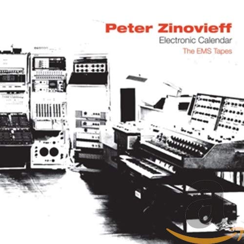
Peter Zinovieff was born in London in 1933. A geologist who filled his home with samples (rocks, not audio) he was fascinated by electronic music, and used his wealth to develop a huge voltage controlled studio that occupied an entire room at his home in Putney.

When this became too unwieldy, he enlisted the help of engineer Dave Cockerell and programmer Peter Grogno, who helped him design an enhanced system. This used two DEC PDP-8 minicomputers to control the voltage-controlled modules of Zinovieff's early synthesizers. Their "MUSYS" system proved reasonably user-friendly,with a QWERTY keyboard and a velocity sensitive piano-style keyboard, much like today's computer-based studios.

Zinovieff's ideas and instruments were incredible. Twenty years before modern computing and sequencing packages, Zinovieff's PDP-8s could store and replay compositions, complete with sound shaping parameters. His software was even capable of twisting the music into bizarre new sounds and effects. In 1968, Zinovieff and Cockerell also invented a form of computer-controlled spectral (or 'additive') synthesis, using a system of 60 resonant filters that could analyse sounds and resynthesize them.

In 1969, when MUSYS became too expensive for Zinovieff alone, he decided to offer it 'to the nation' as a free resource for the arts. To this end, he placed an advertisement in The Times. Fortunately, a gentleman named Don Banks misunderstood this offer and, in return for a cheque for £50, he asked Zinovieff to "make me a synthesizer". So, together with Tristram Cary, a composer for electronic music for TV series such as "Dr Who", Zinovieff and Cockerell created a new company, Electronic Music Studios Ltd, and produced its first synthesizer. Cockerell's "VCS1" was a hand-built rackmount unit with two oscillators, one filter and one envelope. In an era when any synthesizer was, almost by default, a huge modular, this was not thought to be adequate, so the partners enhanced Cockerell's initial ideas, designing an instrument that was small, but powerful and flexible. It was the Voltage Controlled Studios no.3- The VCS3

THE VCS3
--------------
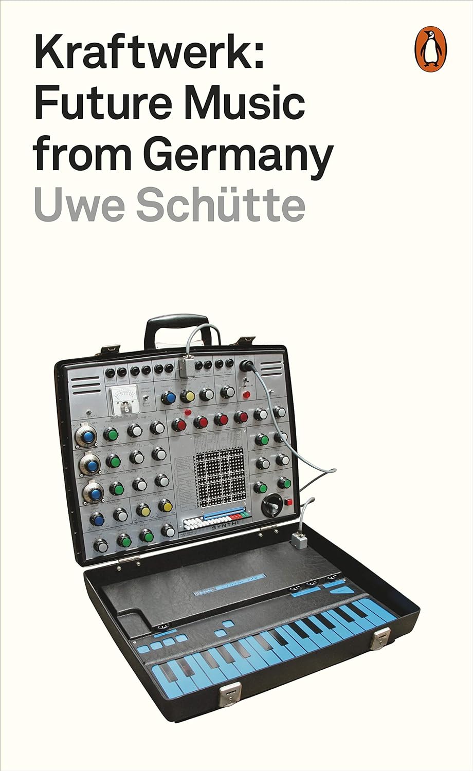
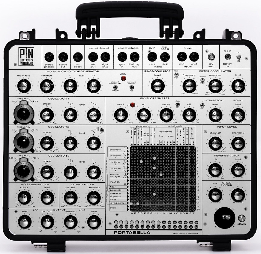
The VCS3 is, essentially, a modular synth that comes in two parts. The synth itself - nicknamed "The Putney" because EMS was located in that part of London - contains the bulk of the audio modules. It also incorporates two power amplifiers and speakers, making it a self-contained sound-effects generator.

Oscillators 1 and 2 are the primary sound sources, and these produce a remarkable range of frequencies, from below 1Hz to around 10KHz. Osc1 produces sine and sawtooth waveforms with a form of rectifying waveshaping for the sine wave. Independent level controls allow you to select the amounts of each waveform in the oscillator's output. The second VCO also produces two simultaneous waveforms, and again it offers independent level controls for each. This time, the waveforms are pulse and triangle waves, with simultaneous waveshaping from 0% to 100% on the former, and from sawtooth to ramp wave on the latter. It's a shame that, on an unmodified VCS3, none of the waveshapers can be voltage controlled, because this would introduce many forms of PWM and dramatically increase the range of sounds available. But there it is... Once selected, a waveform is static. A third VCO is similar to VCO 2, with pulse and triangle waveforms, but its frequency range is concentrated further down the spectrum, lying between 0.025Hz and 500Hz.

An independant section on the panel contains a noise generator, with a level control and a 'colour' control that varies from predominantly low frequencies (red) through 'white' noise, and up to predominantly high frequency (blue) noise. Another section contains the Ring Modulator which, as you would expect, offers just an output level control.

Many players and writers have described the VCS3's filter as a conventional lowpass filter with an 18dB/octave slope, but they are - to some extent - wrong. For one thing, the VCS3 filter exhibits a 'knee' in its cutoff profile; the first octave above the cutoff frequency rolls off at 12dB/octave, but the slope increases to 18dB/octave at frequencies above that. Furthermore, any amount of filter resonance significantly depresses the low frequency gain, so EMS described it as a combined low-pass/band-pass device. At high Response (the EMS term for 'resonance') the filter self-oscillates. This was mind-boggling stuff in the late 60's.

If the filter is unusual, the envelope generator (which EMS called a 'shaper') and its associated VCA are positively arcane. It has six controls. The first is straightforward enough - it's the Attack, which has a range about 2ms to 1s. So far, so good. The next control is laballed "ON", but nowadays we would call this a ustain level "Hold" because it determines the length of time the envelope stays 'high' after you release the gate. Control number three is more recognizable - it's a Decay rate, with a claimed range of 3ms to around 15 seconds. The fourth knob is labelled "OFF" and it determines the delay before autoretriggering of the envelope cycle. Until you understand that this must be in the '10' position (called 'Manual') to play the VCS3 conventionally, things can get very confusing. Indeed, the envelope will auto-repeat at frequencies of up to 60Hz, which is well inside the audio range, so the 'Shaper' can also act as an LFO or even as a deep bass oscillator.

The envelope has two outputs with independent level controls. The first (and the fifrth in the 'shaper' section) is the one that confuses most people: it's the "Trapezoid" level. To understand this, just picture an envelope produced by an AHD (attack/hold/decay) contour generator. This is a shape called a trapezoid. So the Trapezoid Level simply determine the level of the envelope CV. The second level control (the sixth shaper control) is the signal level, and this controls the loudness of any signal passing through the Shaper. There is a lso a large, red ATTACK button, which we would nowadays describe as a manual Gate.

The VCS3 also provides a spring reverb with Mix and Level controls. This is a simple dual-spring device, with a maximum reverberation time of approx. 2 seconds. Unfortunately, when using the VCS3's internal speakers, the reverb howls uncontrollably before the mix gets very dense, and you can only use it to its full potential with external amplification and speakers.

It may not be obvious at first sight, but the VCS3 is a stereo synthesizer with independent output channels A and B that drive the left and right speakers respectively. These have independent level controls, panning controls, and output filter that, depending upon position, attenuate the bass or trable, or porivde a flat response.

Performance controls are limited to the enormous X/Y joystick. This has two controls that govern the X and Y ranges but, unfortunately, its maximum range is about +/-2V, so it's not often that you can plumb the extremes of any parameters it controls. There is also a
voltmeter that allows you to measure any control voltages (which are close to DC) or signal levels (which are AC) within your patches. You can even connect an oscilloscope to a dedicated 1/4" output on the rear.

THE DK1 KEYBOARD
---------------------
The separate DK1 keyboard - known as "The Cricklewood", because that was where Cockerell worked - was as radical as the VCS3 it controlled. Of course, it was monophonic (there were no poly synths in 1969) but it was velocity sensitive, allowing players to add expression in a
way that had hitherto been impossible.

You connect the DK1 to the VCS3 using a dedicated 8-way cable that provides two power rails, two CVs and a Gate pulse for the envelope shaper. To the left of the keyboard itself, two switches control the two output CVs (called 'Channels') produced by the DK1. The first of these has 'Signal' and 'CV1' positions. We'll come to signal in a moment...for now, simply understand that CV1 was what we would now call pitch CV. Hang on... doesn't CV1, and therefore channel 1, produce the same thing? Yes it does, so there's no point in having both switches set to 'CV'.

Now, let's return to that 'Signal' position. The DK1 has a built-in sawtooth oscillator and an associated VCA with frequency, 'spread, level and dynamic range controls. This is a godsend because, with the spread set to '10' the oscillator tracks the keyboard in a conventional 1:1 relationship. In other words, you can play the keyboard and, with everything else set up appropriately, you'll hear the notes that you would expect. This is not necessarily the case when you use the keyboard CV channels. This is because the keyboard CV channels enter the VCS3 through two input level controls marked, sensibly enough, Channel 1 and Channel 2. The problem arises because the 1:1 keytracking occurs somewhere between '6' and '7' on the knobs, and the exact position can fluctuate wildly with the oscillators' temperature, the time of day, and the FTSE100 index. This makes it very tricky to use the VCS3's internal oscillators for correctly pitched melodies. Every time you play the thing, and even after an hour of 'warming up'm you are constantly trimming the tuning and scaling the Channels.

Furthermore, the VCS3 doesn't confirm to either 1V/octave or Hz/V standards used by every other manufacturer, before and after. It uses internal voltages of 0.32V/octave for oscillators 1 and 2, 0.26V/octave for oscillator 3, and 0.20V/octave for the self-oscillating filter. However, because there are CV amplifiers on the internal module inputs, you need to double these figures to 0.64V/octave, 0.52V/octave and 0.40V/octave respectively for external CV sources. Argghhh!!!!

Likewise, the usual 10V peak-to-peak signal levels are eschewed in favour of 3V, 4V and 6V for the oscillators (depending on waveform), 5V for the filter, 3V for the noise generator... and so on. There was nothing about the VCS3 that we would now regard as conventional.

You might think that this is enough of the VCS3's and DK1's oddities, but you would be mistaken. This is because yet discussed its most notable characteristic: the patch matrix.

ENTER THE MATRIX
-----------------
The most important thing to note here is that the VCS3 will remain forever silent unless you stick some pins into the matrix. This is because none of the devices described are connected to eachother unless you use the matrix to determine which signal goes where. Fortunately, the 16x16 matrix allows you to connect any of the VCS3's modules to eachother. For example, let's say that you want to direct the output of oscillator 1 to output channel 1. Since the signal generated by oscillator 1 emerges from the list of sources in row 3, and the input to channel 1 is column A, you simple stick a patch pin in position A3, and the connection is made. Of course, this doesnæt preclude you from sticking more pins in row 3, and yet more in column A, so patches can become very complex, very quickly. Indeed, you can stick 256 pins into all 256 available sockets, but i doubt that it would create a sound. Also, you must remember that, at this point, you have only made a set of connections between modules. Whether you hear a sound, or whether it's a useable one, still depends on the positions on the front panel controls.

Unfortunately, there are three problems with the matrix. The first two are simple to avoid: if mistreated it can become unreliable; and it's very expensive to replace. The third is more fundamental...

The matrix is not "buffered", and this means that, every time you insert a pin into an existing patch, the actions of other patch connections will change to some degree. Let's suppose that you've spent an hour creating a complex patch and getting every knob exactly as you want it. You the decide that you want to add, say, oscillator 2 to the filter input. You insert the appropriate pin - and everything else changes. As you can imagine, this is infuriating.

Now let's turn to the patch pins themselves. These are not simple metal connectors that short between the row and column rails. They are resistors, and there are three types of these in common use. White ones (with a resistance of 2.7kOhm) are the most common, and you can use them for almost anything. However, because the resistors in the pins have a wide (5%) tolerance, they are not suitable for some jobs. In particular, two white pins inserted into I8 and J8 (CV Channel A connected to the pitch CV inputs of VCO1 and 2) will often be sufficiently different to make the oscillators track differently. To overcome this, EMS supplied red pins, also 2.7KOhm, but with 2% tolerance. The third of the common pin colours is green. These pins have a higher resistance than the others, thus reducing the amplitude of a signal considerably. Most often, you use these when you want to attenuate a control signal, such as applying a delicate amount of modulation to a pitch CV input.

If you read some of the conversations flying around the Internet, you might be forgiven for thinking that the VCS3 is no more than a glorified effects unit. In part, this is because few casual users have the patience or knowledge to squeeze conventional musical signals from the instrument. But perhaps more significantly, it's because the VCS3 has four 1/4" inputs on the rear panel - two for microphones, two for line level signals - routed to the Channel 1 and Channel 2 rows on the patch matrix. Because the VCS3 is modular, this is a far more powerful arrangement than the signal inputs on pre-patched monosynths, allowing you to use an external signal as an extra module, maybe as an audio source, a CV source, or even a Gate.

There's another reason why the VCS3 is often regarded as a sound mangler. Because its internal oscillators are so unstable, using external signals (such as generated by the DK1) is often the only way that you can play conventional melodies. So, in many ways, the VCS3's status as an "effects generator extraordinaire" is a classic case of making a virtue out of a necessity."

Scroll through these posts for more history on EMS and of course check out the EMS label below for more.

Wednesday, September 14, 2016

Sonic Detours


Published on Jul 15, 2016 Sonic Detours

Playlist (full descriptions for each further below):
1. Mr. Fingers - Can You Feel It (Sonic Detours Cover)
2. Korg Volca Bass, Keys, Sample and Beats + Waldorf Rocket - Detour #1
3. Korg Volca Jam - Detour #2
4. Korg Volca + Waldorf Rocket Jam - Detour #3
5. Korg Electribe Ambient/Downtempo/Chill Without Beat - Detour #4
6. Jam with Push 2, Waldorf Rocket, Roland JU-06, Korg Volca Bass and Keys - Detour #5
7. Detour #6 - Push 2, Roland JU-06, MicroBrute, Korg Volca Bass, Keys, Beats and Sample
8. Jam with Korg Minilogue, Roland JU-06, MicroBrute, Korg Volca, Ableton Live, Push 2 - Detour #7


1. Mr. Fingers - Can You Feel It (Sonic Detours Cover)

"I bought a Roland JU-06 today and decided to celebrate with a cover of a house music classic.

Gear used:
- Roland JU-06
- Korg Volca Bass
- Korg Volca Keys
- Korg Volca Sample
- Ableton Live 9
- Ableton Push 2
- Novation Launch Control

Ableton live was used for sequencing and mixing only - all synth and drum parts were played on the hardware units."

2. Korg Volca Bass, Keys, Sample and Beats + Waldorf Rocket - Detour #1

Saturday, June 15, 2019

Aphex Twin UNIQUE SUPER RARE RSF SD-140 VINTAGE Drum Machine ?

Note: Auction links are affiliate links for which the site may be compensated.
video upload by urgobenz

"Original samples and patterns by urgobenz.

Pattern n°1 : RSF SD140 (no effect)
Pattern n°2, 3 and 4 : RSF SD140 (with reverb).
Pattern n°5 : RSF SD140 + Korg 700s
Pattern n°6 : RSF SD140 + Chroma Polaris"

03 DMX Krew - Sppoookey [BREAKIN RECORDS]

video upload by edmx


via this auction

This one was spotted and sent in via xonox who noticed the following: "No mention is made in the auction but there is AFX scratched on the surface of the machine. According to Ed DMX (DMX Krew), Aphex Twin used one on his early tracks. Interview here. It is not my auction, i have no insider knowledge on anything either. Is it possible it's indeed one of AFX's drum machines or is it some classic AFX prank ?"

The SD140 has only been featured on the site twice before this post.

The following is the full description from the listing saved for the archives:

"Up for sale a unique extremely rare vintage drum machine. impossible to find it in another place. Many years ago I found this diamond and made the service in a professional workshop. Please note - this is an old gear for the collection and synth enthusiasts, this drum machine is in working condition, but I will not accept any returns and no compensation after the sale - please accept it. These are the first innovative electronic music devices and therefore you can see in the pictures the old technology of plastic coatings and touch buttons have traces of use, but all functions and buttons are well work.- It runs on 220 volt AC.The sound of this beast is very unique, the sound structure and flow are capable of creating incredible emotions and creative potency. The sound is incredibly relevant, I give a detailed description below. The package will be sent internationally, I pack the electronics well — a double strong box and a lot of bubble — look at my seller feedback.

Thursday, April 04, 2019

Silent Way for VCV Rack


Published on Apr 4, 2019 Expert Sleepers

"Silent Way for VCV Rack is a set of modules for integrating hardware synths with Rack's virtual world.

It is mostly a Rack port of key elements of the Silent Way VST/AU/AAX plug-in suite. As such any discussion, tutorials, videos etc. you might find about Silent Way generally applies to the Rack version as well."


Playlist:
1. Silent Way for VCV Rack: Voice Controller
2. Silent Way for VCV Rack: AC Encoder
3. Silent Way for VCV Rack: CV Input
4. Silent Way for VCV Rack: CV To MIDI

http://expert-sleepers.co.uk/vcvrack_silentway.html

Wednesday, March 27, 2019

Rossum Electro-Music Announces Panharmonium Mutating Spectral Resynthesizer


via Rossum Electro-Music

"(Santa Cruz, CA, March 27, 2019)

Rossum Electro-Music has announced that they will be previewing their new Panharmonium Mutating Spectral Resynthesizer Eurorack module at the Synthplex festival in Burbank, CA from March 28th through 31st.

Created by Rossum Electro-Music Software Architect Bob Bliss (who also, as it happens, fathered E-mu’s famed “EOS” Emulator Operating System), Panharmonium is a unique music and sound design tool that analyzes the spectral content of any audio signal and uses that analysis to drive a bank of from 1 to 33 oscillators. Depending on various control settings, Panharmonium can accurately reproduce the input spectrum in real time or modify it in a multitude of wildly creative ways. All with an interface whose immediacy encourages performance and interaction.

Panharmonium input can be anything from a single oscillator to an entire mix (including vocals). From dense, swirling pads and drones that evolve with the input’s changing spectrum, to clock-syncable spectral arpeggiation, to as-yet unnamed harmonic effects, Panharmonium opens up an entirely new world of sonic possibilities.

Additionally, Panharmonium can take a snapshot of an instantaneous spectrum and use that as a complex harmonic oscillator, which can then be modified and modulated by all of Panharmonium’s other controls.

Panharmonium accomplishes its magic though a combination of functional submodules:

Spectral Analyzer

The Spectral Analyzer provides tools for defining the analysis process.

- The Slice parameter sets the rate at which the incoming audio is transformed to spectral data. It can be set by the Slice and Multiplier controls, the Tap button, or by an external clock signal. Very short slice times result in real-time spectral data, while longer times can create rhythmic spectral patterns.

- The Center Freq and Bandwidth controls (and associated CV inputs and attenuverters) control the range of frequencies to be analyzed. The Bandwidth control allows the selection of narrow to wide pass bands on the left side of the pot and narrow to wide notches on the right side of the pot. The ability to sweep the frequency and modify the bandwidth under CV control opens up a wide range of sonic effects.

- The Freeze button lets you freeze the spectral integrator, sustaining the currently analyzed spectrum.

Spectral Modifiers

These controls allow the creative modification the analyzed spectra.

- The Voice parameter controls the number of oscillators (from 1 to 33) used to resynthesize the spectrum.

- The Blur parameter (and associated CV input) is a spectral lag processor that controls how quickly the spectrum can change.

- The Feedback control (and associated CV input) allows one to route the resynthesized audio back into the entire processing chain for subtle or dramatic feedback effects. At its max, the output becomes self-sustaining, even if the input is removed.

Oscillator Bank

The Oscillator Bank resynthesizes the analyzed spectra.

- The Waveform parameter selects the oscillators' waveform. In addition to the usual sine, triangle, sawtooth and pulse waveforms, two special crossfading sine and sawtooth waveforms are included.

- The Freq control tunes the oscillators over a +/-7 semitone range. The frequency is further controlled by the 1V/Oct input and the FM input and attenuverter.

- The Octave control, not surprisingly, shifts the pitch of the output by octaves.

- The Glide parameter sets the amount of polyphonic glide (i.e., each oscillator has its own glide circuit).

- The Mix control (and associated CV input) sets the balance between the original input audio and the resynthesized audio.

Optional Functions

A number of optional functions can be selected by using the Output Mode and Tap buttons.

- Holding the Output Mode button and adjusting the Slice control enables Drums Mode, which optimizes the spectral analysis for drums and other percussive inputs.

- Holding the Output Mode button and adjusting the Center Freq control allows one to instead set the lower frequency of the analysis range.

- Holding the Output Mode button and adjusting the Freq control enables Spectral Warping. In contrast to conventional frequency adjustment, where the harmonic relationships between the spectral elements are preserved, Spectral Warping shifts the harmonic elements individually, producing a variety of clangorous, swarming textures.

- Holding the Tap button and adjusting the Freq control quantizes the resulting frequency adjustments to semitones.

Spectra Memories and Presets

Panharmonium provides 12 user Spectra memories and 12 user Presets (in addition to 12 each factory memories).

- The Spectra memories let you store up to 12 frozen slices. When selected, a spectrum (up to 33 oscillators wide!) replaces any live input and can have its pitch controlled by the 1V/Oct input and FM controls.

- A Preset is a snapshot of all of the module settings, along with the value of any CVs present at the moment the preset is saved.

Panharmonium is 26HP wide and 25mm deep.

Power requirements (max): 140mA +12V, 30mA -12V. Reverse polarity protected.

Panharmonium will be available in early summer from Rossum Electro-Music dealers worldwide at a suggested retail price in the US of $499.00.

More Panharmonium information can be found at the Rossum Electro-Music web site"

Tuesday, April 05, 2011

SDIY Assorted random project ideas

See http://users.ece.gatech.edu/~lanterma/ems11/projectideas_sp11.html. I mirrored this below for the archives as it's on an edu site and they have been known to disappear after interest is gone. There are some interesting details on various synth designs including the Rhodes Chroma VCO, Yamaha CS-80 filter, Roland Jupiter-6 filter, Korg MS-20 sytle VCO, Buchla 148, Tau 1005 Utility VCO, Korg Delta, and more.

Friday, September 28, 2012

Cyndustries FOUR TRANSIENTS MOTM FORMAT

Note: Auction links are affiliate links for which the site may be compensated.

via this auction

"Brand New FOUR TRANSIENTS All-Analog Synthesizer Module in MOTM Format!

Fastest Envelope Generator available in MOTM Format Includes mounting screws and Standard MOTM 4-Pin Power Connector.

The Cynthia® brand, Four Transients Envelope Generator and Sound Processing Module may appear very simple on the surface, but it's simple appearance belies its versatility. Face it, one thing you always come up short on is envelopes. You try using square or triangle waves from LFOs and gates when you need more, but that doesn't really cut it. It would be great if one little module could be the last word in filling this gap.

Four Transients (4T) gives you four simple, independent envelopes that can each be either the AD or AR type. In AR mode, there is an attack phase up to 5v which holds as long as the gate input is held high. The release phase returns the output to 0v when the gate falls. All very familiar, and this is probably the most general and widely used envelope type. You get four of these puppies!

However, the AD mode is something not usually seen. In a conventional ADSR unit, if the gate falls before the attack & decay phases have completed, the unit enters the release phase. This means if you have a slow attack and a brief gate, the envelope might not ever even get off the ground. This is fine if that's what you want. However, Four Transients does something different. The AD transient is self-completing. In response to the rising edge of the GATE input, the envelope goes through the entire attack and decay phases from 0v to +5v and back to 0v, no matter how long that takes. This makes it perfect for those self running, automated patches we all love to create. In AD mode, the attack cannot be re-triggered during its own phase, but is available for re-triggering during the decay phase. You get four of these!

Ins Outs and Knobs

The A knob controls the attack time in the usual way. If you pull it, all times will stretch by about 100 times for those ssssslllllllooooooowwwww events.

The D knob controls the decay time in the usual way. If you pull it, the section changes from AD to AR operation, and the knob controls the release time instead.

The GATE jack inputs any waveform and derives a gate signal from it. If it crosses above +2.5v, it's a gate.

The TIME jack accepts a control voltage that makes all times (for that section) longer or shorter. Higher voltages make things faster (just like a VCO).

The OUT jack, well, you know.

The button is for manual firing and the brightness of the LED in the button tracks the transient.

The UP Output jack, presents a logic high signal during the attack phase of the transient. The behavior is the same in AD and AR modes. This UP PULSE will drop after the attack phase and not hold even though the GATE is still high.

Remember how we said that its simplicity is deceiving? Here's what else this baby can do. In addition to AD and AR modes, you can create ADSR behavior by mixing two transients together. Set one section to AD mode, the other to AR mode. Panning between the two outputs (with a simple mix or pan) varies the sustain level. Set the A's equal. When you do this, you will have simultaneous AD, ADSR, and AR signals available. You can make two ADSRs with this module!

You can create AHD envelopes as well. Patch the PULSE output of one section into the GATE of another. The A knob gives you your Hold time. The second section is set for AR operation and the knobs there will give you your A and D times. You can make two AHD generators with this module! Remember, the AHD will self-complete...

You can create a gate delay with two sections as well. Do the following: Set both transients to AR mode. The A knob on the first will be your delay (set R to zero). Patch the output of this transient to the GATE input of the second. Set A and R to zero to create instantaneous edges. This is what happens; when the input GATE appears, the first transient rises slowly from zero. When it reaches 2.5v, the second transient will fire and stay on creating a delayed gate signal. When the input GATE falls, both transients instantly fall. You can make two gate delays with this module!

Since you get Four Transients, you have enough to create a DADSR or DAHD envelope and still have one section left over!

You can extend the principle outlined above by patching more than 2 sections in series or even in loops. You can get the transients to self-perpetuate in a pseudo quadrature sort of way. Play with staggering the times and modulating the TIME jacks. Swinging rhythms await...

The UP output acts as a one-shot. You can use this to time events. A quick flick of the GATE, and the UP PULSE output remains high for a pre-determined time, controlled by the A knob, and then falls. You could plug that into something...

You can make radical, ultra snappy, hyper-sloped envelopes by feeding an OUTput back into its own TIME jack. When output values are high, the slopes will be steeper and vice versa. This is like self-modulating a VCO. The TIME jack has a huge range and responds exponentially.

How about audio uses. The transients can be made to run so fast that you can use them to process audio. Wha? Yeah, turn any signal into a stream of shaped transient pulses. Run a VCO square wave in and get a constant-time transient pulse per cycle out. Get tracking with the TIME jack if you want it. Changing A and/or D changes the timbre of the pulse, and modulating the TIME jack creates VCF-like effects. Crazy mixed waveforms in, equals crazy, confused transients out. We bet you're not used to listening directly to your envelope generators! (I guess you just broke another rule :)"

Sunday, October 03, 2021

Forms


videos upload by Forms

Saturday, May 22, 2021

Slightly Nasty 4U Modular


This one was spotted and sent in via Martin Gnägi.

Playlist:

Slightly Nasty Modular, Roland MKS-7, and Akai S3000XL
Slightly Nasty Modular - Cinematic Jam
Slightly Nasty Modular - Techno Jam
Five Video Game Covers in Five Minutes
The Model 1011 Discrete VCO
Slightly Nasty Modular Jam
Pit Bull DM-1S - Metal Demo
Slightly Nasty Modular - 8 bar sequence jam
Slightly Nasty modular - dirty cyberpunk bass

Current module line-up via https://www.slightlynasty.com:

Tuesday, May 07, 2019

The Division Department 01/IV ANALOG DRUM SYNTH


The first batch of the new 01/IV ANALOG DRUM SYNTH will be limited to a run of 50.

"01/IV by The Division Department is a 4-channel analog drum synthesizer capable of synthesizing a wide palette of sounds. From usual drum hits like kicks, toms, snares, claps, hi-hats and cymbals to unusual and complex sounds like drones and weird modulated creations. The provided MIDI implementation lets the 01/IV be triggered via MIDI, which makes it a powerful piece of equipment in a setup.

The concept of 01/IV is unique as it has four identical voice channels with all the power of synthesizing various type of drum sounds. Any channel can play a kick, a cymbal, toms and congas, or even a bassline. Channels can even be combined, can modulate each others in pairs (FM) or can be layered to form complex sounds. All these achieved with a flexible routing system composed of slide switches and carefully calibrated synthesizer elements.

01/IV inherited genes from legendary drum machines and drum synthesizers like the Pollard Syndrum, the Roland 808 & 909, and Pearl Syncussion SY-1. It has a true analog audio path, but also added a very flexible digital modulation system of a multi-function LFO, ramp and retrigger generator.

Key Features:

60 panel controls: Knobs - Switches - Triggers Buttons
4 Voices - Chromatic via midi
Drone Mode
Midi note triggers and partial Midi CC controls
Mix / Individual outputs
Compact size / Light weight

Some details captured from The Division Department website for the archives follow. See The Division Dapartment label for additional posts.

Tuesday, January 18, 2011

Vulcan Harp & Theremin (1929 RCA Theremin)


YouTube via copperleaves | January 18, 2011 |

"This is called THE KATRIC ARK and it is one of a series of 12 compositions for Vulcan harp and theremin. Since the Vulcan harp was introduced by artist and visionary Wah Ming Chang more than 40 years ago, it has evolved considerably, along with the technology involved with its manufacture. It is acoustic, electroacoustic and electronic (it is the electronic component that permits such things as the playing of complex harmonies, glide pitch shifts, etc.).

As a sculptor, Chang molded the instrument to fit the human body, and it is great to hold because it is so wonderfully ergonomic. This particular harp has 26 strings (copper, brass and silver) and is played with finger picks. There are no steel strings and the instrument does not use magnetic pickups like electric guitars. It also does not need to be plugged into anything so there are no annoying cables to get in the way. It transmits directly to its amplifier and speakers by means of an antenna integrated into the pin column (the extended curved vertical arm that holds the tuning pins). The two speakers you see in the video are JBL JRX-125 monitors.

As a concept, the characteristics of "Vulcan music" are determined by the remarkable capabilities of the Vulcan harp which include many of the possibilities of the classical instruments of India. The sound of the Vulcan harp has been described as a combination of harp, lute, violin and sitar. If you add to this everything that is possible with the use of the shift disc and the harmonic valves (the seven button controls - one for each note of the diatonic scale - riding above the brass plate) you have an extraordinary number of combinations that can be explored. The harmonic valves are all level-sensitive (each responds to three degrees of left hand finger pressure applied to them: touch, half, and full) and this determines the harmony applied to the vibrating strings. Octave displacement is played by multiple valve configurations depending on the register in which the harpist wants to play.

There is also a "tapper control" incorporated into the Vulcan harp for generating complex polyrhythms but it is not used in this particular composition. The "tapper" is the knob that sits just behind the lowest bass strings on the upper edge of the instrument facing the harpist. It can be silently programmed just before a piece is played by drumming the fingers of the left hand on the knob in the exact rhythm combination you want to hear applied to your sound once you begin to play. The instrument will loop the rhythm continuously throughout the piece (or until you squelch it).

The theremin in this video is the 1929 RCA that once belonged to Hollywood thereminist Dr. Samuel Hoffman. It was used by Dr. Hoffman on the soundtracks of many classic science fiction films of the 1950's, so I thought it would be appropriate to use it here. If you are curious about this 1929 theremin, I am featured in the 20TH CENTURY FOX 2-disc DVD "special edition" of the re-issue of the original 1951 science fiction masterpiece, THE DAY THE EARTH STOOD STILL. There are already several videos on YouTube of me playing this instrument (and some from the 1950's of Dr. Hoffman as well) so after the solo theremin section at the beginning of the composition, I concentrated entirely on showing the Vulcan harp. There are very few Vulcan harps in the world and even fewer musicians who can actually play them, so I thought people might might like to see it.

PLEASE NOTE: the recording of this composition was done directly to a Roland VS-2400CD. There were no FX added to the instruments other than the usual EQ and a small amount of reverb. No peripherals, no MIDI modules, overdubs or computers were used at any time in the recording process."
NEXT PAGE HOME


Patch n Tweak
Switched On Make Synthesizer Evolution Vintage Synthesizers Creating Sound Fundlementals of Synthesizer Programming Kraftwerk

© Matrixsynth - All posts are presented here for informative, historical and educative purposes as applicable within fair use.
MATRIXSYNTH is supported by affiliate links that use cookies to track clickthroughs and sales. See the privacy policy for details.
MATRIXSYNTH - EVERYTHING SYNTH